Aerospace Applications Guide
A comprehensive guide to metallographic analysis for aerospace applications, covering titanium and superalloy preparation, fatigue and creep damage assessment, coating analysis, and industry-specific standards and requirements.
Table of Contents
Introduction
Aerospace applications demand the highest standards in material quality, performance, and reliability. Metallographic analysis plays a critical role in ensuring that aerospace components meet these stringent requirements. This guide covers specialized techniques and considerations for preparing and analyzing aerospace materials, including titanium alloys, nickel-based superalloys, and coated components.
Aerospace metallography presents unique challenges due to the critical nature of components, the complex microstructures of advanced materials, and the need to assess damage mechanisms such as fatigue and creep. Proper sample preparation is essential to reveal true microstructures without introducing artifacts that could lead to incorrect conclusions about material condition or failure mechanisms.
This guide addresses the key aspects of aerospace metallography:
- Preparation techniques for titanium and superalloys
- Assessment of fatigue and creep damage
- Analysis of protective coatings and surface treatments
- Compliance with aerospace industry standards
.JPG&w=1200&q=75)
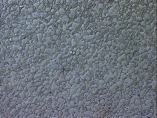
Aerospace titanium alloy microstructure showing complex phase structure. Proper metallographic preparation is essential to reveal the true microstructure and assess material condition for critical aerospace applications. 400X magnification (DIC).
Titanium and Superalloy Preparation
Titanium alloys and nickel-based superalloys are the workhorses of aerospace applications, used in critical components such as turbine blades, compressor discs, and structural elements. These materials require specialized preparation techniques to reveal their complex microstructures accurately.
Titanium Alloy Preparation
Titanium alloys, particularly Ti-6Al-4V (Grade 5), are widely used in aerospace due to their excellent strength-to-weight ratio and corrosion resistance. However, titanium is highly reactive and requires careful handling during preparation.
Ti-6Al-4V titanium alloy microstructure showing alpha-beta phase structure. Proper preparation reveals the grain boundaries and phase distribution critical for aerospace applications.
For detailed titanium preparation procedures, refer to our comprehensive Titanium Preparation Guide. Key considerations for aerospace titanium components include:
- Sectioning: Prefer a precision saw with a diamond wafering blade for small or critical sections; for abrasive cutoff, use a medium-hard-bond blade rated for hard non-ferrous metals (the titanium category) at typical surface speeds (~2,500-4,500 SFM) with light feed and copious flood coolant to minimize heat generation and deformation
- Mounting: Cold mounting with epoxy is preferred to avoid thermal effects on microstructure
- Grinding: Progressive grinding (120, 240, 400, 600 grit) with light pressure to avoid work-hardening
- Polishing: Diamond polishing (9 μm → 3 μm → 1 μm) followed by a chemo-mechanical final polish of colloidal silica with hydrogen peroxide (1:5 H₂O₂:silica)—plain colloidal silica leaves a stubborn deformation layer on titanium
- Etching: Kroll's reagent for general microstructure; 10% oxalic acid electrolytic at 5 V for β-phase imaging on α-β and β alloys

A medium-hard-bond abrasive blade rated for hard non-ferrous metals (titanium, zirconium) — the dedicated titanium category. Thin blades (0.5-1.0 mm) minimize heat generation and deformation during sectioning.
Critical Note: Titanium forms surface oxides easily. Minimize exposure to air after polishing and etch promptly. Many titanium etchants contain hydrofluoric acid (HF), which requires proper safety equipment including gloves, safety glasses, and calcium gluconate gel for first aid.
Nickel-Based Superalloy Preparation
Nickel-based superalloys such as Inconel, Waspaloy, and René alloys are used in high-temperature aerospace applications, particularly in turbine engines. These materials have complex microstructures with multiple phases and require carefulpreparation to reveal all features.
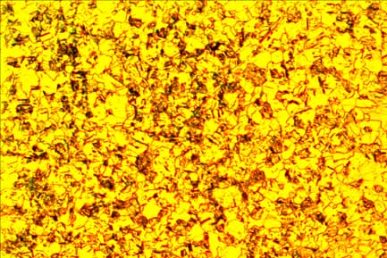
Hastelloy superalloy microstructure showing complex phase structure. Superalloys contain multiple phases including precipitates and carbides that must be properly revealed through careful preparation and etching. 200X magnification (DIC).
For detailed superalloy preparation procedures, refer to our Nickel Alloys Preparation Guide. Key considerations for aerospace superalloys include:
- Sectioning: Use an abrasive blade rated for nickel and cobalt superalloys (a medium-hard-bond Al₂O₃ or CBN wheel) at typical abrasive-cutoff surface speeds (~2,500-4,500 SFM) with light, steady feed and continuous flood cooling
- Mounting: Epoxy mounting is preferred to avoid thermal damage to sensitive microstructures
- Grinding: Progressive grinding through 120, 240, 400, 600, 800 grit with light pressure
- Polishing: Extended diamond polishing sequence (9 μm → 6 μm → 3 μm → 1 μm) with appropriate cloths for each stage
- Etching: Marble's reagent or Modified Kalling's for general structure; electrolytic etching (e.g., 5% chromic acid at 5 V) for gamma prime imaging, depending on the specific superalloy and features to be revealed
Microstructure Features: Superalloys typically contain gamma prime (γ')precipitates, carbides, and sometimes topologically close-packed (TCP) phases. Properetching is essential to reveal these features and assess their size, distribution, and morphology, which directly affect material properties.
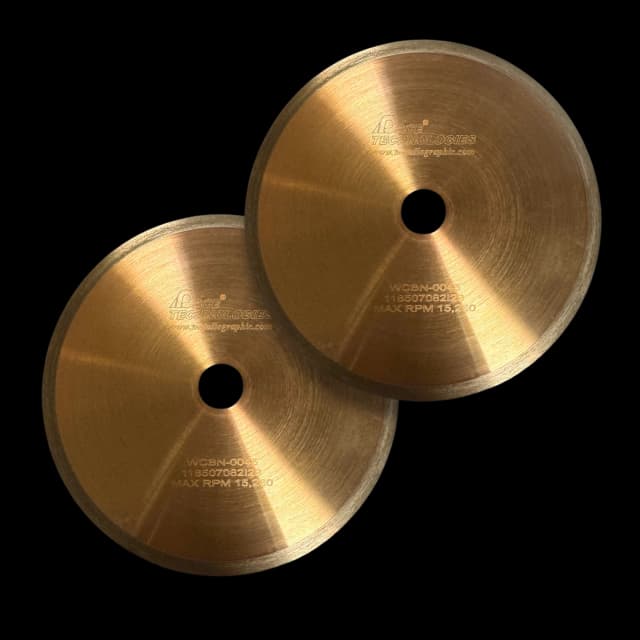
CBN and medium-hard-bond Al₂O₃ blades rated for nickel and cobalt superalloys (the right category for Inconel, Hastelloy, and Co-base alloys).
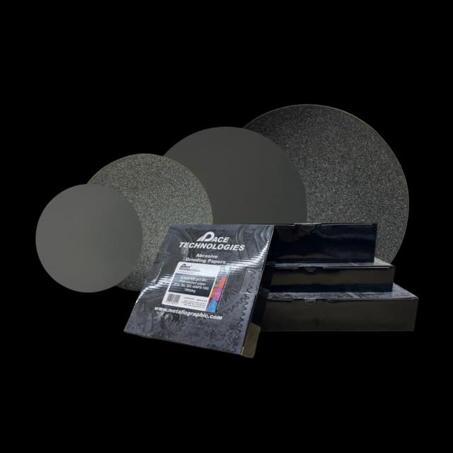
Silicon carbide grinding papers for progressive grinding of superalloys.
Common Aerospace Alloys
Titanium Alloys
- Ti-6Al-4V (Grade 5): Most common aerospace titanium alloy, used in structural components
- Ti-6Al-2Sn-4Zr-2Mo (Ti-6242): High-temperature titanium alloy for engine components
- Ti-3Al-2.5V (Grade 9): Used in tubing and hydraulic systems
- Commercially Pure Titanium (Grade 2): Used in non-critical applications requiring corrosion resistance
Nickel-Based Superalloys
- Inconel 718: Precipitation-hardened superalloy for turbine discs and blades
- Inconel 625: Solid-solution strengthened, used in exhaust systems
- Waspaloy: Used in high-temperature turbine components
- René 41: High-strength superalloy for turbine blades
- Hastelloy X: Used in combustion chambers and afterburners
Example Products: Abrasive Blades for Aerospace MaterialsMedium-hard-bond blades rated for hard non-ferrous metals (titanium), plus Al₂O₃/CBN blades rated for nickel and cobalt superalloys
For purchasing options and product specifications, see commercial supplier website.
Example Products: Silicon Carbide Grinding Papersappropriate SiC papers in all grit sizes for progressive grinding of aerospace materials
For purchasing options and product specifications, see commercial supplier website.
Fatigue and Creep Damage Assessment
Fatigue and creep are two of the most critical failure mechanisms in aerospace components. Proper metallographic preparation and analysis are essential for identifying and assessing damage from these mechanisms.
Fatigue Damage Assessment
Fatigue failures result from cyclic loading below the material's ultimate strength. In aerospace applications, components are subjected to millions of loading cycles, making fatigue a primary concern.
For comprehensive failure analysis techniques, refer to our Failure Analysis Guide.
Identifying Fatigue Damage
- Fracture Surface Examination: Beach marks or striations indicate progressive crack growth
- Crack Initiation Sites: Often at stress concentrators, surface defects, or material anomalies
- Multiple Initiation Sites: Common in high-cycle fatigue
- Final Fast Fracture Region: Shows the final overload mechanism
Metallographic Preparation for Fatigue Analysis
When preparing samples for fatigue analysis:
- Preserve Fracture Surfaces: Document and protect fracture surfaces before sectioning
- Cross-Sectional Analysis: Prepare sections perpendicular to the fracture surface to examine crack path
- Multiple Sections: Prepare sections at different locations to understand crack progression
- Careful Polishing: Avoid over-polishing that could remove fine crack features
- Appropriate Etching: Use etchants that reveal grain boundaries and phases to understand crack path
Microstructural Indicators of Fatigue
- Persistent Slip Bands: Fine lines indicating localized plastic deformation
- Grain Boundary Cracking: In high-temperature fatigue
- Phase Transformation: In materials like titanium, fatigue can cause phase changes
- Surface Damage: Fretting, wear, or corrosion that initiated fatigue
Creep Damage Assessment
Creep is time-dependent deformation under sustained load at elevated temperatures. In aerospace applications, creep is particularly important in turbine components operating at high temperatures.
Identifying Creep Damage
- Grain Boundary Cavitation: Voids forming at grain boundaries, particularly triple points
- Elongated Grains: Grains elongated in the direction of applied stress
- Intergranular Cracking: Cracks following grain boundaries
- Phase Coarsening: Precipitates (e.g., γ' in superalloys) coarsen during creep
- Recrystallization: New grains forming in highly deformed regions
Metallographic Preparation for Creep Analysis
Creep damage assessment requires careful preparation to preserve and reveal damage features:
- Section Orientation: Prepare sections both parallel and perpendicular to the stress axis
- Preserve Cavities: Use gentle polishing to avoid filling or smearing grain boundary cavities
- Deep Etching: May be needed to reveal grain boundary damage
- Multiple Magnifications: Examine at various magnifications to identify different stages of creep damage
- Comparison with Unused Material: Compare with material in the unused condition to identify changes
Creep Damage Classification
Stage I (Primary Creep): Rapid initial deformation, decreasing rate
Stage II (Secondary Creep): Steady-state creep with constant rate
Stage III (Tertiary Creep): Accelerating deformation leading to failure
Microstructural Indicators:
- Early stage: Minor grain boundary sliding, no visible damage
- Intermediate stage: Isolated grain boundary cavities
- Advanced stage: Interconnected cavities, microcracks
- Final stage: Macroscopic cracking, imminent failure
Quantitative Assessment
Quantitative assessment of creep damage may include:
- Cavity density (number per unit area)
- Grain boundary coverage by cavities
- Grain aspect ratio (length/width)
- Precipitate size and distribution
- Remaining life estimation based on damage level
Coating Analysis for Aerospace Components
Aerospace components often have protective coatings applied to enhance performance, durability, or resistance to high temperatures and corrosion. Proper metallographic preparation is essential to analyze these coatings without damaging them.
Types of Aerospace Coatings
Thermal Barrier Coatings (TBCs)
Applied to turbine blades and vanes to protect against high temperatures. Typically consist of a ceramic topcoat (e.g., yttria-stabilized zirconia) over a bond coat (e.g., MCrAlY, where M = Ni, Co, or both).
Environmental Barrier Coatings (EBCs)
Protect ceramic matrix composites from water vapor and oxidation at high temperatures.
Corrosion-Resistant Coatings
Applied to protect components from environmental degradation, including aluminum coatings, chromate conversion coatings, and anodized layers.
Wear-Resistant Coatings
Hard coatings such as chromium, tungsten carbide, or diamond-like carbon applied to reduce wear in moving components.
Sample Preparation for Coating Analysis
Coating analysis requires specialized techniques to preserve coating integrity and reveal the coating-substrate interface clearly. For comprehensive coating preparation techniques, refer to our Coating and Surface Treatment Analysis Guide.

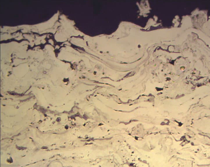
Thermal spray coating cross-section showing coating structure and interface with substrate. Proper preparation preserves the coating integrity and reveals the interface clearly.
Sectioning
- Use light feed rates to minimize damage to brittle coatings
- Consider using a precision saw with diamond blade for hard ceramic coatings
- Cut perpendicular to the coating surface for thickness measurement
- Use adequate coolant to prevent thermal damage
Mounting
- Cold mounting is preferred to avoid thermal damage to coatings
- Use low-shrinkage epoxy resins to maintain edge retention
- Consider vacuum impregnation for porous coatings
- Ensure proper orientation to preserve coating-substrate interface
Grinding and Polishing
Special care is needed during grinding and polishing to avoid:
- Coating Delamination: Use light pressure and appropriate abrasives
- Edge Rounding: Maintain edge retention with proper mounting and technique
- Relief: Avoid over-polishing that creates relief between coating and substrate
- Smearing: Soft coatings may smear; use appropriate polishing cloths and lubricants
- Pullout: Brittle coatings may pull out; use gentle techniques
Recommended Preparation Sequence for Coatings
- Grinding: Start with 240-320 grit, progress through 400, 600, 800 grit with light pressure
- Diamond Polishing: 9 μm → 6 μm → 3 μm → 1 μm with appropriate cloths
- Final Polish: 0.05 μm colloidal silica or alumina, but be careful not to over-polish
- Etching: May be needed to reveal coating structure, but many coatings are best examined unetched
Polycrystalline diamond compound for polishing coatings without creating relief.
Various polishing pads and cloths for different polishing stages of coatings.
Coating Characterization
Thickness Measurement
- Measure at multiple locations to assess uniformity
- Use calibrated microscope with appropriate magnification (typically 200-500X)
- Report average, minimum, and maximum thickness
- Compare with specification requirements
Microstructure Analysis
- Coating Structure: Columnar, equiaxed, or layered
- Porosity: Amount and distribution of pores
- Bond Coat Condition: Oxidation, interdiffusion with substrate
- Interface Quality: Adhesion, defects, interdiffusion zone
- Substrate Effects: Microstructural changes in substrate near interface
Nickel-aluminum coating microstructure showing coating structure and interface with substrate. The coating-substrate interface is clearly visible, demonstrating proper preparation technique. 500X magnification.
Defect Identification
- Cracks (vertical, horizontal, or branching)
- Delamination at interface
- Oxidation of bond coat
- Spallation or loss of coating
- Inclusions or contamination
- Non-uniform thickness
Service-Induced Changes
Coatings in service may undergo changes that affect performance:
- Thermal Cycling: Can cause cracking and spallation
- Oxidation: Formation of thermally grown oxide (TGO) at bond coat interface
- Interdiffusion: Elements diffusing between coating and substrate
- Phase Changes: Microstructural evolution during service
- Erosion: Loss of coating material from particle impact
Example Products: Coating Analysis EquipmentSpecialized equipment for coating analysis including precision sectioning and mounting systems
For purchasing options and product specifications, see commercial supplier website.
Industry-Specific Standards and Requirements
Aerospace metallography must comply with numerous industry standards and specifications. Understanding and following these standards is critical for ensuring component quality and regulatory compliance.
ASTM Standards
Sample Preparation Standards
- ASTM E3: Standard Practice for Preparation of Metallographic Specimens
- ASTM E407: Standard Practice for Microetching Metals and Alloys
- ASTM E1920: Standard Guide for Metallographic Preparation of Thermal Sprayed Coatings
- ASTM E2014: Standard Guide for Preparation of Plastics and Polymeric Specimens for Microstructural Examination
Analysis and Testing Standards
- ASTM E112: Standard Test Methods for Determining Average Grain Size
- ASTM E883: Standard Guide for Reflected-Light Photomicrography
- ASTM E1245: Standard Practice for Determining the Inclusion or Second-Phase Constituent Content of Metals by Automatic Image Analysis
- ASTM E1823: Standard Terminology Relating to Fatigue and Fracture Testing
Aerospace Industry Standards
SAE/AMS Standards
- AMS 2300: Aircraft Quality Steel - Cleanliness, Aircraft Quality
- AMS 2301: Aircraft Quality Steel - Cleanliness, Premium Aircraft Quality
- AMS 2759: Heat Treatment of Steel Parts, General Requirements
- AMS 2770: Heat Treatment of Aluminum Alloy Raw Materials
- AMS 2801: Heat Treatment of Titanium Alloy Raw Materials
NADCAP (National Aerospace and Defense Contractors Accreditation Program)
NADCAP accreditation is often required for aerospace suppliers. Key requirements include:
- Documented procedures for all preparation steps
- Calibrated equipment with traceable standards
- Qualified personnel with appropriate training
- Quality control measures and documentation
- Regular audits and compliance verification
Material-Specific Requirements
Titanium Alloys
- AMS 4928: Titanium Alloy, Sheet, Strip, and Plate (Ti-6Al-4V)
- ASTM B265: Standard Specification for Titanium and Titanium Alloy Strip, Sheet, and Plate
- Requirements for alpha case depth measurement
- Microstructure evaluation per material specification
Superalloys
- AMS 5662: Nickel Alloy, Corrosion and Heat-Resistant, Bars, Wire, and Forgings (Inconel 718)
- AMS 5708: Nickel Alloy, Corrosion and Heat-Resistant, Sheet, Strip, and Plate (Inconel 625)
- Gamma prime (γ') size and distribution requirements
- Grain size specifications
- Carbide distribution evaluation
Documentation Requirements
Aerospace metallography requires comprehensive documentation:
- Sample Identification: Traceability to source material and component
- Preparation Records: Detailed documentation of all preparation steps
- Micrographs: High-quality images with proper labeling and scale bars
- Measurements: Quantitative data with uncertainty estimates
- Reports: Comprehensive reports with conclusions and recommendations
- Compliance Statements: Verification of compliance with applicable standards
Quality Assurance
Quality assurance measures for aerospace metallography include:
- Regular calibration of equipment (microscopes, hardness testers, etc.)
- Reference samples for verification of preparation quality
- Round-robin testing for interlaboratory comparison
- Personnel qualification and training records
- Document control and revision management
- Non-conformance tracking and corrective action
Refer to our ASTM Standards Reference for more information on relevant standards.
Best Practices for Aerospace Metallography
Following best practices ensures accurate, reliable results that meet aerospace industry requirements.
Sample Preparation Best Practices
- Minimize Artifacts: Avoid introducing scratches, contamination, or deformation
- Consistent Techniques: Use standardized procedures for reproducibility
- Appropriate Magnification: Use appropriate magnification for the features of interest
- Multiple Sections: Prepare multiple sections when possible to ensure representative analysis
- Preserve Evidence: Document and preserve critical features before destructive testing
Analysis Best Practices
- Systematic Approach: Follow a structured methodology for consistent results
- Quantitative When Possible: Use quantitative measurements rather than qualitative assessments
- Statistical Analysis: Collect sufficient data for statistical significance
- Comparison with Standards: Compare results with material specifications and standards
- Documentation: Maintain comprehensive records of all observations and measurements
Safety Considerations
- Chemical Safety: Many aerospace materials require hazardous etchants (HF, strong acids)
- Personal Protective Equipment: Always use appropriate PPE including gloves, safety glasses, and lab coats
- Ventilation: Ensure adequate ventilation when using volatile or hazardous chemicals
- Emergency Procedures: Know emergency procedures and have appropriate first aid supplies (e.g., calcium gluconate for HF exposure)
- Waste Disposal: Follow proper procedures for disposal of hazardous materials
For comprehensive safety information, refer to our Safety Fundamentals Guide.
Common Pitfalls to Avoid
- Over-Polishing: Can remove fine features or create relief
- Insufficient Etching: May not reveal all microstructural features
- Over-Etching: Can obscure fine details or create artifacts
- Contamination: Cross-contamination between samples can lead to incorrect conclusions
- Inadequate Documentation: Poor documentation can compromise traceability and compliance
- Ignoring Standards: Not following applicable standards can result in non-compliance
Explore More Procedures
Browse our comprehensive procedure guides for material-specific preparation methods and get personalized recommendations.