Composites Preparation
A comprehensive guide to preparing composite material samples for metallographic analysis, covering specialized techniques to avoid fiber pullout, maintain fiber orientation, and reveal matrix-fiber interfaces.
Introduction
Composite materials, including fiber-reinforced composites (FRCs), present unique challenges in metallographic preparation. These materials consist of two or more distinct phases, typically a matrix material (polymer, metal, or ceramic) reinforced with fibers (carbon, glass, aramid, or ceramic). The heterogeneous nature of composites requires specialized techniques to preserve the integrity of both phases and reveal the true microstructure.

Polymer-graphite composite, 200X magnification. This image demonstrates proper composite preparation with intact fibers, clear matrix-fiber interfaces, and minimal pullout artifacts.
Key Challenge: Composites are particularly susceptible to fiber pullout, delamination, and interface damage during preparation. The matrix and fiber phases often have vastly different mechanical properties, making uniform preparation difficult. Careful attention to each step is essential to maintain fiber orientation and reveal matrix-fiber interfaces.
Common composite types include carbon fiber reinforced polymers (CFRP), glass fiber reinforced polymers (GFRP), metal matrix composites (MMC), and ceramic matrix composites (CMC). Each type requires specific considerations, but the fundamental principles of careful sectioning, appropriate mounting, gentle grinding, and careful polishing apply to all.
The goal of composite preparation is to achieve a flat, scratch-free surface that preserves the original structure, maintains fiber orientation, reveals the matrix-fiber interface, and allows for accurate microstructural analysis. Unlike monolithic materials, composites often rely more heavily on contrast from polishing rather than etching to reveal structure. The difference in hardness between matrix and fiber phases creates natural contrast when polished correctly, with softer matrices polishing faster than harder fibers, creating slight relief that enhances visibility under the microscope.
Composite Material Characteristics
- • CFRP (Carbon Fiber Reinforced Polymer): Stiff, brittle carbon fibers in polymer matrix — not especially hard, but highly abrasive — requires careful handling to prevent fiber fracture and pullout
- • GFRP (Glass Fiber Reinforced Polymer): Glass fibers in polymer matrix; the polymer matrix (not the glass) is sensitive to thermal damage during sectioning
- • MMC (Metal Matrix Composites): Hard ceramic reinforcement — most often SiC, Al₂O₃, or B₄C particles or whiskers, sometimes ceramic or carbon fibers — in a metal matrix (Al, Mg, Cu, Ti); the matrix phase can be etched with conventional reagents. Common examples include aluminum matrix composites and titanium matrix composites
- • CMC (Ceramic Matrix Composites): Fibers in ceramic matrix, very hard, requires diamond abrasives throughout
Sectioning
Sectioning composite materials requires careful consideration of the matrix and fiber properties. The goal is to minimize damage to both phases and avoid delamination or fiber pullout. Cutting parameters must be optimized to prevent excessive heat generation, which can damage polymer matrices or cause thermal degradation.
Cutting Parameters
- Cutting Speed: On a precision wafering saw (preferred for polymer-matrix composites): 1,500-3,000 RPM with a light applied load (100-500 g). On a conventional abrasive cutoff machine: standard surface speeds (2,500-4,500 SFM) with a low, steady feed - excess feed causes delamination far more often than excess speed
- Blade Selection: a thin precision diamond wafering blade (resin-bond or low-concentration metal-bond, 0.3-0.5 mm) is generally preferred for polymer-matrix work; a thin (0.5-1.0 mm) abrasive cut-off wheel rated for fiber-reinforced composites is acceptable when a precision saw is unavailable. Use diamond blades for very hard ceramic reinforcements
- Cooling: Continuous cooling with water or cutting fluid is essential. Use adequate flow rate to prevent thermal damage to polymer matrices
- Feed Rate: Slow, steady feed (0.5-1.0 mm/min on a precision saw) to avoid excessive pressure and delamination
- Cutting Direction: Consider fiber orientation - cut perpendicular to fiber direction when possible to minimize pullout
Thin abrasive cut-off blades (0.5-1.0 mm) minimize kerf loss and reduce the risk of delamination in composite materials. Choose a blade rated for soft to medium-hard materials with minimal heat generation.
Composite-Specific Sectioning Considerations
By Composite Type
- CFRP (Carbon Fiber Reinforced Polymer): A precision diamond wafering blade is preferred; a thin abrasive blade rated for fiber composites at low feed is acceptable. Carbon fibers are stiff and abrasive and wear a blade's bond matrix over time. Monitor blade condition and re-dress or replace when cutting efficiency decreases. Use continuous water cooling.
- GFRP (Glass Fiber Reinforced Polymer): Same blade options as CFRP. Glass fibers are brittle and can shatter if cut too aggressively. The polymer matrix is the heat-sensitive constituent - keep coolant flow high and feed low throughout the cut.
- MMC (Metal Matrix Composites): Use a fiber-composite-rated abrasive blade or a diamond blade depending on reinforcement hardness. Abrasive wheels are fine for soft particulate or short-fiber reinforcements in aluminum matrix composites and steel-matrix systems; diamond blades are recommended for SiC, B4C, or Al₂O₃ reinforcements.
- CMC (Ceramic Matrix Composites): Use diamond blades exclusively, with slow feed and rigid clamping. These materials are very hard and abrasive - diamond blades are essential for clean cuts.
Best Practices
- Use thin blades (0.3-1.0 mm) to minimize kerf loss and reduce heat generation
- Maintain constant cooling throughout the cut to prevent matrix damage - flow rate should be sufficient to keep the cut area flooded
- Avoid excessive pressure - let the blade do the work. Excessive force can cause delamination or fiber damage
- For polymer matrix composites, keep the feed rate low and the coolant flow high to prevent melting or thermal degradation
- For metal matrix composites with very hard reinforcements (SiC, B4C), consider using diamond blades
- Support the sample properly to prevent flexing and delamination - use appropriate fixtures or clamps
- Consider the fiber orientation when planning the cut direction - cutting perpendicular to fiber direction minimizes pullout
- Mark the fiber orientation on the sample before cutting if it's not obvious, to maintain reference during preparation
Important: Polymer matrix composites are particularly sensitive to heat. Excessive cutting speed or insufficient cooling can cause matrix melting, fiber damage, or interface degradation. Always use adequate cooling and monitor the cutting process carefully.
Example Products: Composite-Rated Abrasive BladesThin abrasive blades (0.5-1.0 mm) designed for cutting fiber-reinforced composite materials with minimal heat generation and delamination
For purchasing options and product specifications, see commercial supplier website.
Mounting
Mounting composite samples requires special consideration to preserve the structure and prevent damage to the matrix-fiber interface. The mounting material must provide adequate support without causing thermal damage or chemical interaction with the composite constituents.
Mounting Considerations
- Temperature Sensitivity: Polymer matrix composites require low-temperature mounting to avoid matrix damage
- Pressure Control: Use moderate pressure to avoid crushing or delamination
- Edge Retention: Ensure good edge retention to preserve fiber ends and interfaces
- Chemical Compatibility: Avoid mounting materials that may react with composite constituents
Compression Mounting
For metal matrix composites and some ceramic matrix composites, compression mounting with epoxy resins is preferred over phenolic — not for thermal reasons (both resin families cure in the same 150-180°C range) but because epoxy has lower shrinkage, better adhesion to the sample, and better edge retention, all of which matter when the matrix-fiber interface near the mount boundary is the analysis target. Compression mounting at these temperatures is not appropriate for polymer matrix composites — use cold mounting instead.
- Clean the sample thoroughly to remove cutting fluid and debris
- Place sample in mounting press with a compression-grade epoxy resin
- Apply standard pressure (typically around 4,200 psi; roughly 2,900 psi is sometimes used for delicate composites)
- Heat to 150-180°C and hold for 5-8 minutes
- Cool slowly to room temperature under pressure to minimize thermal stress
Cold Mounting
Cold mounting is strongly recommended for polymer matrix composites (CFRP, GFRP) to completely avoid thermal exposure. This method is essential for temperature-sensitive materials and eliminates the risk of matrix degradation, fiber-matrix interface damage, or delamination from thermal cycling.
Cold mounting epoxy resins cure at room temperature, eliminating thermal damage risk for polymer matrix composites. These resins provide excellent edge retention and support for composite samples.
- Clean and dry the sample thoroughly - ensure no cutting fluid remains
- Place in mounting cup with a two-part castable epoxy resin
- Mix resin and hardener according to manufacturer instructions
- Pour into mounting cup, ensuring sample is properly positioned
- Allow to cure at room temperature (typically 6-12 hours, or overnight for best results)
- Cold mounting eliminates risk of thermal damage to polymer matrices and interfaces
Special Consideration: For composites with soft matrices, use mounting materials with similar hardness to prevent relief during polishing. For composites with high fiber volume fractions, choose mounting materials with good edge retention properties.
Vacuum impregnation is mandatory for CMCs (and any composite with porosity).For ceramic matrix composites, fiber loss at the matrix-fiber interface is the primary defect mode, and inadequate impregnation guarantees it. Draw a full vacuum (>25 inHg) with a low-viscosity epoxy and, where equipment allows, follow with positive pressure (1-4 bar) to drive resin into the pore network. For dense fiber tows, multi-cycle impregnation (vacuum, vent, vacuum again) improves penetration. Polymer-matrix and metal-matrix composites with internal voids or high porosity (e.g., RTM-process CFRP, sintered MMC) also benefit from vacuum impregnation, though it's not always strictly required.
Grinding
Grinding composite materials requires careful attention to prevent fiber pullout and maintain fiber orientation. The heterogeneous nature of composites means that grinding must be gentle enough to avoid damaging the softer phase (usually the matrix) while still effectively removing sectioning damage.
Abrasive choice for MMC — switch to a diamond ladder when the reinforcement is SiC, Al₂O₃, or B₄C. SiC papers grinding SiC-reinforced aluminum (the most common MMC class) causes the worst possible artifact: SiC particles liberate from the paper and embed in the soft Al matrix, where they are visually indistinguishable from the SiC reinforcement particles you're actually trying to image. Volume-fraction measurements and reinforcement-distribution analysis are corrupted in ways that aren't obvious without EDS. Use a diamond ladder (75 → 30 → 15 → 9 µm on diamond-impregnated discs or films) for any MMC where the reinforcement is harder than ~9 Mohs — SiC, Al₂O₃, B₄C, WC, ceramic fibers. The SiC ladder below is acceptable for polymer-matrix composites (CFRP, GFRP), where SiC abrasive cuts the polymer matrix cleanly and the carbon/glass fibers don't share the SiC-on-SiC embedment pathology.
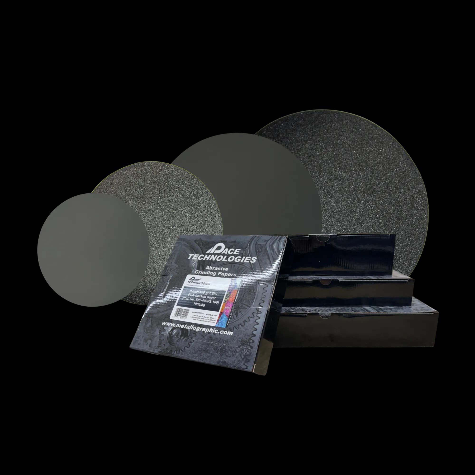
Silicon carbide (SiC) grinding papers in various grit sizes for progressive grinding. Use light pressure and rotate sample 90° between each grit to prevent fiber pullout.
Grinding Sequence
- 120 grit: Remove sectioning damage (30-60 seconds per step) - use very light pressure. Skip this step for CFRP/GFRP and start at 240 grit - 120 grit fractures fibers and creates deep subsurface damage that takes many more steps to remove
- 240 grit: Remove previous scratches (30-60 seconds); the starting grit for polymer-matrix composites
- 400 grit: Further refinement (30-60 seconds)
- 600 grit: Final grinding step (30-60 seconds)
- 800 grit: Optional for composites requiring finer surfaces (20-40 seconds)
Grinding Parameters
- Pressure: Very light pressure (1-3 lbs per sample) to prevent fiber pullout
- Rotation: Rotate sample 90° between each grit to ensure complete scratch removal
- Water Flow: Continuous water flow to remove debris and prevent loading
- Speed: 240-300 RPM for grinding wheels
- Time: Shorter times per step compared to metals - monitor frequently
Grinding Tips for Composites
- • Use very light pressure throughout - composites are more sensitive than metals
- • Monitor the surface frequently to detect fiber pullout early
- • Use fresh grinding papers - loaded papers can cause excessive pullout
- • For soft matrix composites, consider starting with finer grits (240 or 400)
- • Ensure all scratches from previous grit are removed before proceeding
- • Avoid excessive grinding time which can cause relief between matrix and fiber
Example Products: Silicon Carbide Grinding Papersappropriate SiC papers in all grit sizes for consistent grinding of composite materials
For purchasing options and product specifications, see commercial supplier website.
Polishing
Polishing is perhaps the most critical step in composite preparation. Careful polishing is essential to avoid fiber damage, prevent pullout, and reveal the matrix-fiber interface. The goal is to achieve a flat surface with good contrast between phases, often relying on polishing-induced contrast rather than etching.
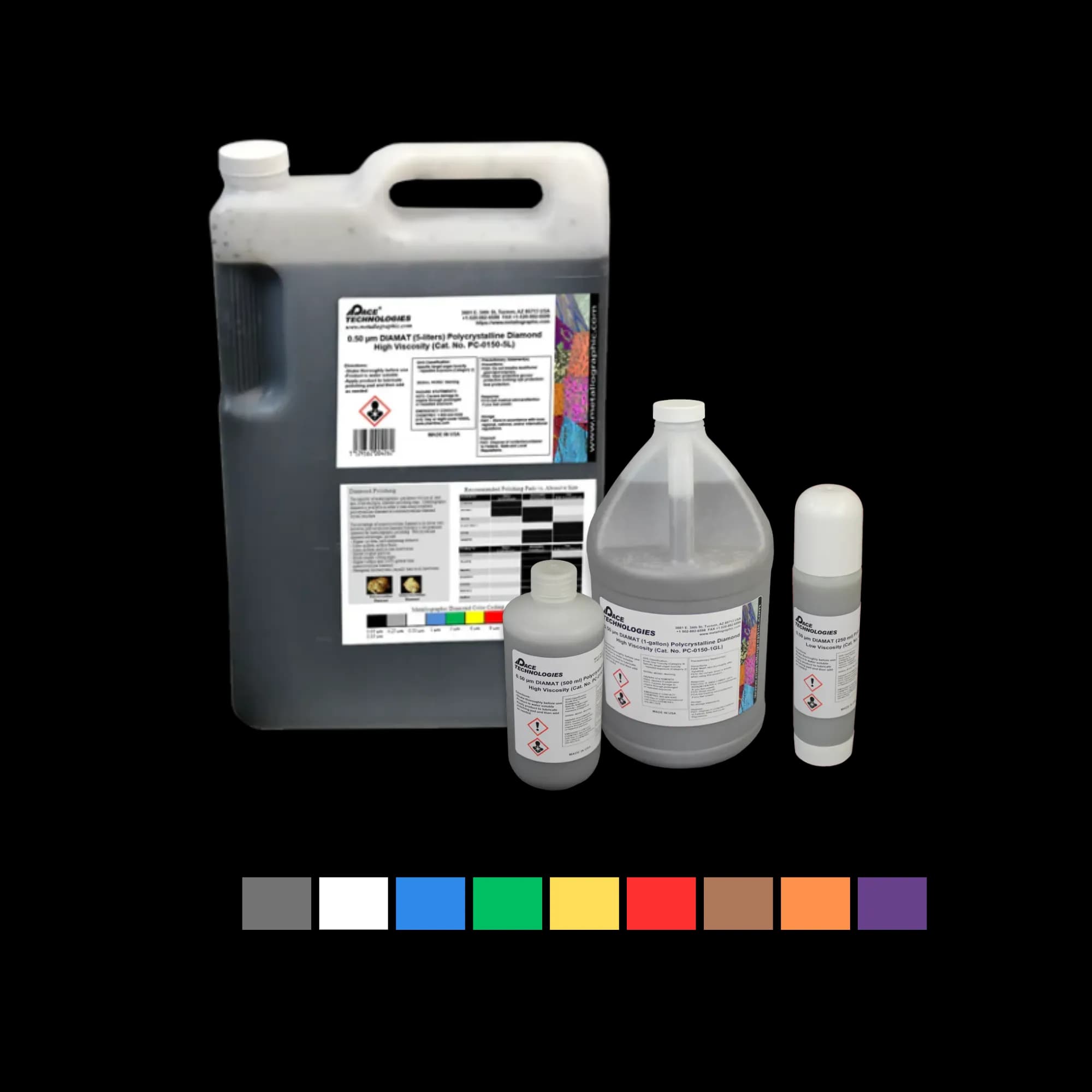
Polycrystalline diamond compound provides consistent cutting action for composite materials.
Hard pads (hard woven and hard non-woven types) are the canonical choice for composite polishing through 1 µm. Soft napped cloths conform around fibers and cause the pullout they appear to prevent.
Pad hardness — this is the lever for fiber pullout, and it is the opposite of what intuition suggests.Use hard pads through the diamond ladder, not soft cloths. Soft napped cloths conform around hard fibers (carbon, glass, SiC, B₄C) and grip them on multiple sides; when the platen rotates, the lateral force on the fiber-matrix bond exceeds bond strength and the fiber tears free — exactly the pullout the soft cloth was supposed to prevent. Hard pads make point contact only and shear cleanly through the field, leaving the fiber-matrix interface intact. This applies equally to CFRP, GFRP, MMC, and adhesive-joint composites.
Diamond Polishing Sequence
Use polycrystalline diamond suspensions for consistent cutting action. Stay on hard pads through 3 µm and ideally through 1 µm — soft napped cloths cause more pullout than they prevent.
- 9 μm diamond: 2-4 minutes on a hard woven or hard non-woven pad. Polycrystalline diamond gives more consistent cutting.
- 3 μm diamond: 2-4 minutes on a hard non-woven or low-nap pad. If pullout appears, reduce pressure — do not switch to a softer pad.
- 1 μm diamond: 2-3 minutes on a hard or medium-hard pad. Avoid napped pads at this step.
- 0.25 μm diamond: Optional — 1-2 minutes on a medium-hard pad. Only if needed for very fine surfaces.
Final Polishing
Final polishing with colloidal silica creates the natural contrast between matrix and fiber phases that is essential for composite microstructural analysis.
- For polymer-matrix composites (CFRP, GFRP): 0.05 μm colloidal silica, 30-90 s on a medium-hard pad (chemotextile or synthetic suede — not a soft napped cloth). Minimal pressure (1-2 lbs).
- For metal-matrix composites (Al, Mg, Cu, Ti matrix): 0.04-0.05 μm colloidal silica with an H₂O₂ addition on a chemotextile pad, 3 min + flush (typical: 5-10% H₂O₂ for Cu matrix; 30% H₂O₂ added at roughly 1:5 to the silica for Ti matrix). The H₂O₂ provides the chemo-mechanical attack that lifts the smeared metal-matrix layer plain silica leaves behind — without it, the matrix surface looks polished but won't take Keller's / Kroll's / Nital cleanly.
- Vibratory polishing with colloidal silica (1-4 hours, very low load) is an excellent alternative final step for any composite where mechanical pullout has been a recurring problem.
- Rinse with water, then ethanol, and air-dry — avoid wiping which can lever fibers out.
- Final polish often provides sufficient contrast without etching. The differential polishing rates of matrix and fiber create natural relief that reads cleanly under brightfield and especially DIC.
Polishing Parameters
- Pressure: Light pressure (3-5 lbs at 9 μm, tapering to 1-2 lbs by the final step) — critical to prevent fiber pullout. Use the minimum pressure that maintains contact.
- Speed: 120-150 RPM for diamond polishing. Lower speeds (100-120 RPM) may be beneficial for very sensitive composites.
- Cloth Selection: Hard pads through 3 µm and ideally through 1 µm (hard woven or hard non-woven). Medium-hard chemotextile or synthetic suede for final. Avoid soft napped cloths for any composite step — they conform around fibers and cause the pullout they appear to prevent.
- Lubricant: Polycrystalline diamond suspension in water-based lubricant. High-viscosity suspensions help maintain diamond particles in contact with the surface.
- Direction: Consider fiber orientation — polish perpendicular to fiber direction when possible. For random fiber orientations, use gentle circular motions.
- Time: Monitor frequently. Shorter times per step are often better than extended polishing which causes relief at the matrix-fiber interface.
Critical Consideration: Fiber pullout is the most common problem in composite polishing. Use very light pressure on hard pads, and monitor the surface frequently. If pullout occurs, return to a previous polishing step and use even lighter pressure — not a softer cloth. The matrix-fiber interface must be preserved to reveal the true microstructure.
Maintaining Fiber Orientation
Throughout the polishing process, maintain awareness of fiber orientation. Polishing parallel to fiber direction can cause excessive pullout, while polishing perpendicular to fibers helps maintain interface integrity. For random fiber orientations, use gentle, circular motions with very light pressure.
Example Products: Colloidal Silica0.05 μm colloidal silica for final polishing to create natural contrast between matrix and fiber phases
For purchasing options and product specifications, see commercial supplier website.
Etching
Etching options for composite materials are often limited, especially for polymer matrix composites. Many composites rely primarily on contrast achieved through careful polishing rather than chemical etching. However, some etching may be beneficial for metal matrix composites or for revealing specific features.
Important Note: Many composite materials, especially polymer matrix composites, do not respond well to traditional metallographic etchants. The contrast between matrix and fiber phases is often best achieved through careful polishing that creates natural contrast from the different hardnesses of the phases.
Etching Considerations
- Polymer Matrix Composites: Generally not etched — rely on polishing contrast. Applies to CFRP and GFRP.
- MMC — Aluminum matrix (SiC/Al, Al₂O₃/Al, B₄C/Al): Aluminum matrix composites are etched with Keller's reagent (2 mL HF + 3 mL HCl + 5 mL HNO₃ + 190 mL H₂O) by swab, 5-30 s. Keller's attacks the Al matrix only — the SiC, Al₂O₃, or B₄C reinforcement particles appear unaffected. This is the correct outcome, not a failed etch — selective matrix etching is exactly what reveals the matrix-reinforcement boundary and the reinforcement distribution. Examine in bright field. HF safety: fume hood, HF-rated PPE, calcium gluconate gel.
- MMC — Titanium matrix (SiC/Ti): Etch the Ti matrix with Kroll's reagent (2 mL HF + 6 mL HNO₃ + 92 mL H₂O) by swab, 5-15 s. SiC reinforcement remains unetched. Same HF safety as above.
- MMC — Other matrices: Use the standard etch for the matrix metal: NH₄OH + H₂O₂ for Cu matrix; acetic-glycol for Mg matrix; Nital for steel matrix. The reinforcement phase will appear unetched in each case.
- Ceramic Matrix Composites: Typically examined unetched; phase identification is by SEM/EDS. Limited chemical etching options.
- Interface Revelation: For most composites, polishing-induced contrast reveals interfaces better than etching — particularly under DIC.
Polishing-Induced Contrast
For most composites, the best contrast is achieved through careful polishing rather than etching. The different hardnesses of the matrix and fiber phases create natural contrast when polished properly. Soft matrices polish faster than hard fibers, creating slight relief that enhances visibility under the microscope. Keep this relief to the minimum that produces usable contrast: under differential interference contrast (DIC) microscopy, height differences below about 0.1 μm already give excellent phase contrast, while much larger relief distorts fiber geometry and biases quantitative measurements such as fiber volume fraction and void content. Slightly larger relief aids brightfield viewing, but excessive relief is a defect, not a contrast technique.

Polymer-graphite composite, as-polished (no etching), 200X magnification. This image demonstrates excellent contrast achieved through careful polishing alone, with clear distinction between matrix and fiber phases.
Limited Etching Options
When etching is attempted for metal matrix composites, use standard etchants for the matrix material (e.g., Keller's reagent for aluminum matrix composites, Nital for steel matrix). However, etching times should be reduced, and the process should be monitored carefully to avoid over-etching the matrix or damaging the fiber-matrix interface.
Etching Procedure (if applicable)
- Ensure sample is clean and dry before etching
- Apply etchant sparingly using cotton swab (for metal matrix composites only)
- Etch for shorter times than for monolithic materials (5-15 seconds)
- Monitor etching progress carefully
- Rinse immediately with water, then alcohol
- Dry with compressed air
Best Practice
For most composite materials, focus on achieving excellent polishing quality rather than relying on etching. The natural contrast from polishing often provides better results than attempting to etch heterogeneous materials. Use differential interference contrast (DIC) microscopy to enhance contrast if available.
Troubleshooting
Common Issues and Solutions
Problem: Fiber Pullout
Symptoms: Holes or gaps where fibers should be, missing fiber ends, disrupted fiber orientation, visible voids in the microstructure
Root Causes: Soft napped polishing cloths (the dominant cause — soft pads conform around fibers and grip them laterally, tearing them free during platen rotation), excessive polishing pressure, insufficient grit progression, polishing parallel to fiber direction, over-polishing.
Solutions: Switch to harder pads (hard woven or hard non-woven) — this is counterintuitive but is the canonical fix. Reduce polishing pressure (1-2 lbs per sample). Ensure proper grit progression (don't skip grits). Polish perpendicular to fiber direction when possible. Use polycrystalline diamond for more consistent cutting. Vibratory polishing with colloidal silica (1-4 hours, very low load) is excellent for stubborn cases. Monitor the surface frequently with low-power microscopy to detect pullout early.
Problem: Loss of Fiber Orientation
Symptoms: Fibers appear misaligned, original orientation not preserved
Solutions: Use lighter pressure during all steps, avoid excessive grinding/polishing, maintain consistent sample orientation, mark fiber direction before sectioning, use slower cutting speeds during sectioning
Problem: Poor Interface Revelation
Symptoms: Matrix-fiber interface not visible, unclear boundaries between phases
Solutions: Improve polishing quality, use final polish with colloidal silica, ensure flat surface (no relief), use differential interference contrast (DIC) microscopy, adjust lighting conditions, ensure proper contrast from polishing
Problem: Soft Matrix Damage
Symptoms: Excessive relief around fibers, smearing of matrix material, distorted matrix structure
Solutions: Use very light pressure, shorter polishing times, start with finer grits if matrix is very soft, use mounting material with similar hardness to the matrix. Note that for fibrous composites the answer is not softer cloths — keep hard pads and reduce pressure or shorten time instead.
Problem: Delamination
Symptoms: Separation of layers, gaps between plies, visible delamination cracks
Solutions: Reduce cutting speed during sectioning, use adequate cooling, support sample properly during cutting, use vacuum impregnation during mounting if necessary, avoid excessive pressure during mounting
Problem: Insufficient Contrast
Symptoms: Matrix and fiber phases difficult to distinguish, poor visibility of interfaces, uniform appearance under brightfield illumination
Root Causes: Over-polishing (too much relief removed), insufficient final polish, matrix and fiber have similar hardness, improper polishing technique
Solutions: Improve final polishing quality with 0.05 μm colloidal silica on a medium-hard chemotextile or synthetic suede pad, use DIC (differential interference contrast) microscopy to enhance contrast, adjust lighting conditions (try oblique illumination), ensure proper surface flatness (no excessive relief), consider using polarized light for certain fiber types (glass fibers), verify polishing has created natural contrast between phases, reduce final polish time if over-polishing has occurred, ensure proper grit progression was followed
Problem: Thermal Damage
Symptoms: Melted or degraded matrix, discoloration, interface damage
Solutions: Use cold mounting instead of compression mounting, reduce cutting speed, increase cooling during sectioning, use lower mounting temperatures, avoid excessive heat during any preparation step
Explore More Procedures
Browse our comprehensive procedure guides for material-specific preparation methods and get personalized recommendations.