Heat Treatment Verification
A comprehensive guide to verifying heat treatment effectiveness through metallographic analysis, including case depth measurement, decarburization detection, and microstructure validation for different heat treatment processes.
Table of Contents
Introduction
Heat treatment verification is a critical application of metallography that ensures materials have been properly heat treated to achieve desired properties. Through careful sample preparation and microstructural analysis, metallographers can verify that heat treatment processes have been executed correctly and that materials meet specified requirements.
This guide covers the metallographic techniques used to verify heat treatment effectiveness, including case depth measurement, decarburization detection, and microstructure validation. Proper sample preparation is essential for accurate verification, as preparation artifacts can mask or mimic heat treatment effects.

Martensite microstructure in 1095 steel after water quenching, etched with Vilella's reagent. This demonstrates the characteristic needle-like structure of martensite formed through proper heat treatment.
Key Principle: Heat treatment verification requires careful sample preparation that preserves the true microstructure and avoids artifacts that could be mistaken for heat treatment effects. Proper sectioning, mounting, grinding, polishing, and etching are all critical for accurate analysis.
Verifying Heat Treatment Effectiveness
Heat treatment verification involves multiple approaches to confirm that materials have been properly processed. The primary methods include microstructural examination, hardness testing, and dimensional analysis.
Microstructural Examination
The most direct method for verifying heat treatment is examining the microstructure:
- Phase identification: Verify the presence of expected phases (martensite,bainite, pearlite, ferrite, etc.)
- Grain size: Measure and compare grain size to specifications
- Phase distribution: Assess uniformity and distribution of phases
- Microstructural gradients: Identify transitions in case-hardened materials
- Anomalies: Detect unexpected phases or microstructural features
Hardness Testing
Hardness measurements provide quantitative verification of heat treatment effectiveness:
- Surface hardness: Verify surface hardness meets specifications
- Hardness profiles: Measure hardness gradients in case-hardened materials
- Core hardness: Verify core properties are within acceptable ranges
- Uniformity: Check hardness consistency across the sample
For detailed information on preparing samples for hardness testing, see our Hardness Testing Preparation guide.
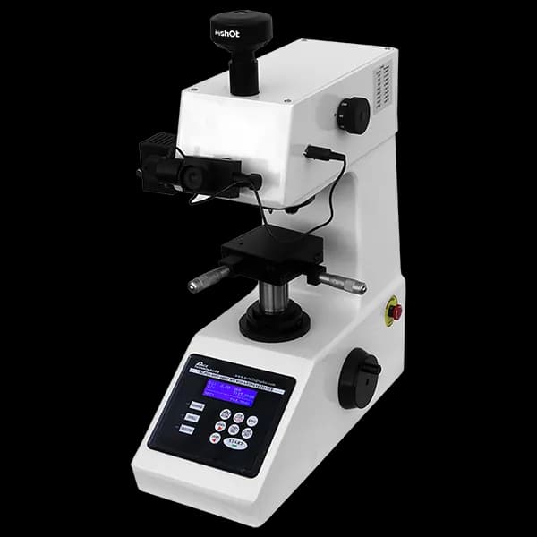
Microhardness testers (Vickers and Knoop) are essential for accurate case depth measurements. The elongated Knoop indenter is particularly useful for testing near edges and in thin case layers.
Example Products: Microhardness TestersVickers and Knoop microhardness testers for case depth measurements and hardness profiling
For purchasing options and product specifications, see commercial supplier website.
Dimensional Analysis
Heat treatment can cause dimensional changes that must be verified:
- Case depth: Measure effective case depth and total case depth
- Distortion: Assess dimensional changes from heat treatment
- Layer thickness: Measure thickness of surface-modified layers
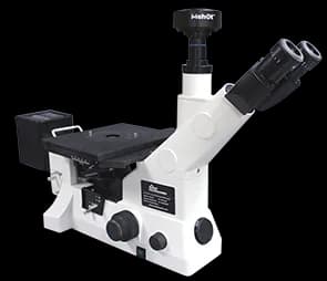
High-quality metallographic microscopes with calibrated eyepieces enable accurate case depth and dimensional measurements. Essential for microstructural examination and verification.
Verification Checklist
Before beginning verification, ensure you have:
- Heat treatment specifications and requirements
- Material composition and grade
- Expected microstructure for the heat treatment
- Hardness requirements (if applicable)
- Case depth requirements (for case-hardened materials)
- Reference samples (if available) for comparison
Case Depth Measurement
Case depth measurement is critical for verifying case-hardening processes such as carburizing,nitriding, carbonitriding, and induction hardening. Accurate measurement requires proper sample preparation and careful analysis.
Types of Case Depth
Different definitions of case depth are used depending on the application:
- Total case depth: Distance from surface to point where microstructure becomes indistinguishable from core
- Effective case depth: Distance from surface to point where hardness reaches a specified value (typically 50 HRC or 550 HV)
- Hardness case depth: Depth to a specific hardness level
- Microstructural case depth: Depth based on microstructural changes
Sample Preparation for Case Depth Measurement
Proper preparation is essential for accurate case depth measurements:
- Sectioning: Cut perpendicular to the case-hardened surface to reveal the full case depth profile
- Mounting: Use a hard, low-shrinkage compression-mounting resin — glass-filled epoxy gives the best edge retention, which is critical for accurate surface measurements (plain phenolic wears faster than the steel and rounds the edge)
- Grinding and polishing: Follow standard procedures with emphasis on maintaining flatness and edge retention
- Edge retention: Critical for accurate surface hardness measurements and microstructural analysis at the surface
For detailed edge retention techniques, refer to the Hardness Testing Preparation guide.
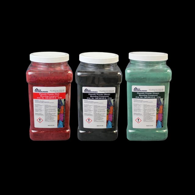
Hard compression-mounting resins — glass-filled epoxy in particular — provide the edge retention critical for accurate case depth and decarburization measurements.
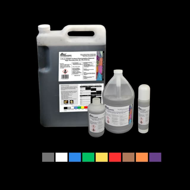
High-quality diamond polishing compounds create scratch-free surfaces essential for microhardness testing and accurate microstructural analysis.
Measurement Methods
Microhardness Traverse Method
The most accurate method for measuring effective case depth:
- Prepare sample with excellent edge retention; polish through 1 μm diamond and finish with colloidal silica — micro-Vickers and Knoop indents require a deformation-free, colloidal-silica-finished surface for legible indent corners
- Test on the polished, unetched surface (or after only a very light etch) — heavy etching degrades indent legibility
- Make microhardness measurements at increasing depths from the surface, per ASTM E384
- Start at or very near the surface (typically 0.05-0.1 mm), but keep each indent at least 3× its diameter away from the specimen edge
- Continue measurements at regular intervals (0.05-0.1 mm spacing), maintaining indent spacing of at least 2.5× the indent diagonal — stagger indents laterally in a zigzag pattern if the depth increments would otherwise place indents too close together
- Continue until hardness reaches core level
- Plot hardness vs. depth and determine effective case depth
Knoop hardness is often preferred for case depth measurements because the elongated indenter allows testing closer to edges and provides better resolution in thin case layers. This is particularly important when measuring the effective case depth, which requires accurate hardness measurements starting at or very near the surface. Orient the long Knoop diagonal parallel to the surface so the indent stays within a narrow depth band.

Properly prepared and etched steel microstructure showing ferrite and pearlite. Such preparation quality is essential for accurate case depth measurements and microstructural analysis.
Microstructural Method
Visual measurement based on microstructural changes:
- Etch sample to reveal case/core boundary
- Examine at appropriate magnification (typically 100-200x)
- Measure distance from surface to where microstructure changes
- Use calibrated eyepiece or image analysis software
This method is less precise than hardness traverse but faster and useful for quality control.
Combined Method
The most comprehensive approach combines both methods:
- Use microhardness traverse for quantitative effective case depth
- Use microstructural examination to verify case/core boundary
- Compare results to ensure consistency
- Document both measurements in report
Common Case-Hardening Processes
| Process | Typical Case Depth | Key Microstructural Features | Preferred Etchant |
|---|---|---|---|
| Carburizing | 0.5-3.0 mm | High-carbon martensite in case, ferrite/pearlite in core | Nital (2-4%) |
| Nitriding | 0.1-0.8 mm | Compound layer (white layer), diffusion zone | Nital, or unetched |
| Carbonitriding | 0.1-0.8 mm | Martensite with retained austenite | Nital (2-4%) |
| Induction Hardening | 1-10 mm | Martensite in case, original core structure | Nital (2-4%) |
| Flame Hardening | 1-10 mm | Martensite in case, original core structure | Nital (2-4%) |
Best Practice: For case depth measurements, prepare multiple samples and take measurements at several locations to account for variations. Report both average and range of measurements.
Decarburization Detection
Decarburization is the loss of carbon from the surface of steel during heat treatment, resulting in a soft surface layer that can compromise component performance. Detecting and measuring decarburization is essential for quality control.
What is Decarburization?
Decarburization occurs when carbon diffuses out of the steel surface during heating in oxidizing or decarburizing atmospheres. This creates a surface layer with lower carbon content than the core material.
- Partial decarburization: Gradual decrease in carbon content from surface to core
- Total decarburization: Complete loss of carbon at the surface, resulting in pure ferrite layer
- Selective decarburization: Decarburization of specific phases (e.g., pearlite)
Microstructural Identification
Decarburization is identified by microstructural changes:
- Ferrite layer: Pure ferrite at the surface (total decarburization)
- Reduced pearlite: Decreased pearlite content near surface (partial decarburization)
- Grain size differences: Often coarser ferrite grains in decarburized zone
- Microhardness gradient: Lower hardness at surface, increasing toward core

Pearlite and ferrite microstructure. Decarburization would appear as a surface layer with reduced pearlite content or pure ferrite, requiring careful preparation and etching to reveal.
Sample Preparation for Decarburization Detection
Proper preparation is critical for accurate decarburization measurement:
- Sectioning: Cut perpendicular to the surface to reveal the full decarburization depth
- Mounting: Use hard mounting materials for edge retention
- Grinding and polishing: Standard procedures with emphasis on edge retention and flatness
- Minimize artifacts: Avoid preparation artifacts that could be mistaken for decarburization
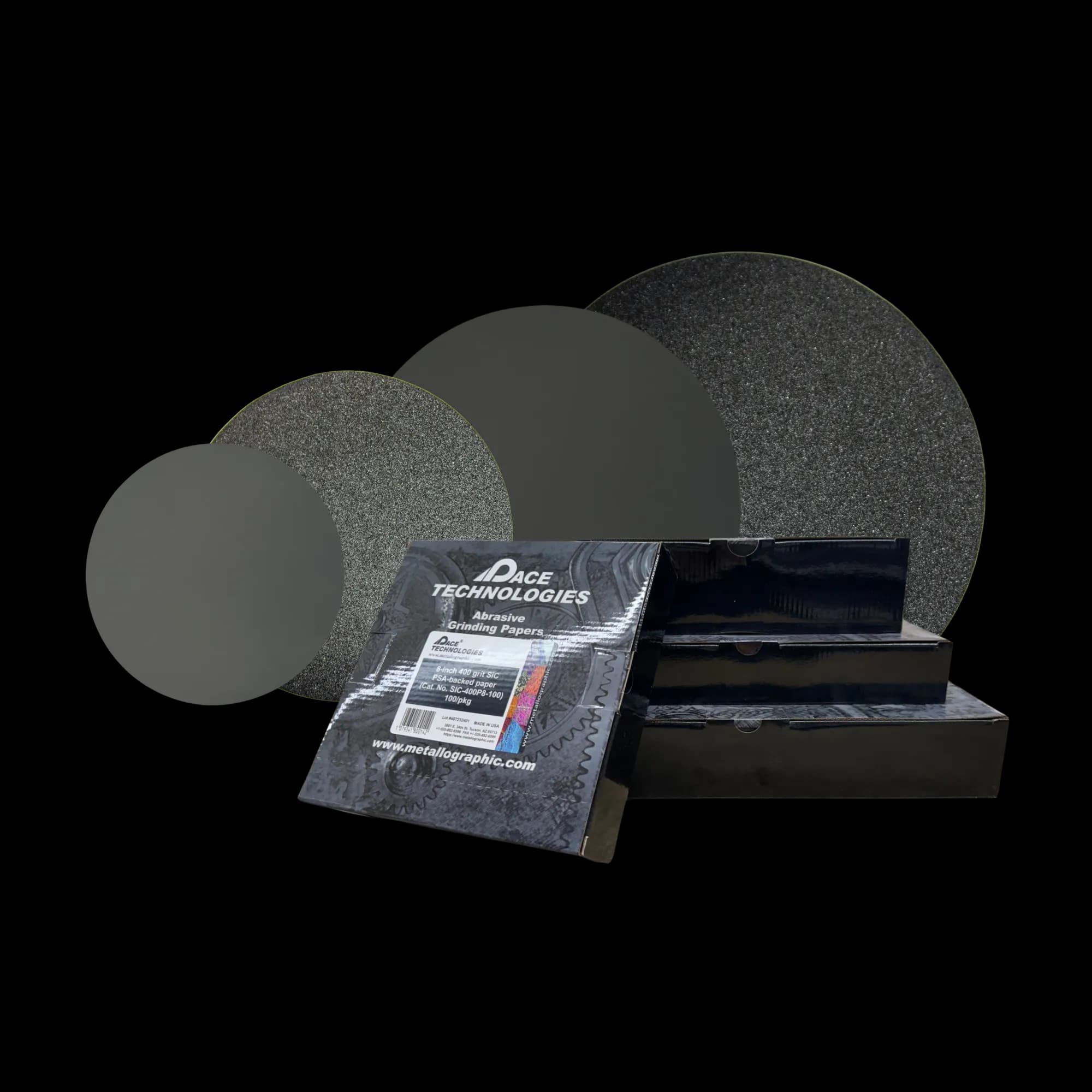
Progressive silicon carbide grinding papers remove sectioning damage while preserving surface features essential for decarburization detection.
Example Products: Silicon Carbide Grinding PapersProgressive grinding papers for removing sectioning damage while preserving surface features
For purchasing options and product specifications, see commercial supplier website.
Etching for Decarburization
Proper etching is essential to reveal decarburization:
- Nital (2-4%): Most common etchant for carbon steels
- Picral: Alternative etchant that better reveals pearlite
- Light etching: Use lighter etching to avoid over-etching the decarburized surface
- Multiple etches: May need to try different etchants or etching times to optimize contrast
Measurement Methods
Decarburization depth estimation is standardized in ASTM E1077 (Standard Test Methods for Estimating the Depth of Decarburization of Steel Specimens), which covers both the microstructural (screening) and microhardness (quantitative) approaches below.
Microstructural Method
Visual measurement of decarburization depth:
- Etch sample to reveal microstructure
- Examine at 100-200x magnification
- Identify the depth where microstructure returns to normal
- Measure from surface to this point
- Take measurements at multiple locations
Microhardness Method
Quantitative measurement using hardness traverse:
- Make microhardness measurements from surface into core
- Identify depth where hardness reaches core level
- This depth represents the effective decarburization depth
This method is more objective and quantitative than microstructural measurement.
Acceptance Criteria
Decarburization limits depend on application:
- General applications: Typically 0.1-0.5 mm maximum
- Critical applications: Often 0.05-0.1 mm maximum
- Bearing applications: Very strict limits, often near zero
- Specifications: Always refer to material or component specifications
Important: Decarburization can be removed by machining, but this must be accounted for in component design. Verify that sufficient material remains after machining to remove decarburization.
Microstructure Validation for Different Heat Treatment Processes
Different heat treatment processes produce characteristic microstructures that can be verified through metallographic examination. Understanding expected microstructures is essential for accurate verification.
Quenching and Tempering
Quenching and tempering produces martensite that is tempered to various hardness levels:
- As-quenched: Martensite with possible retained austenite
- Low temper (150-250°C): Tempered martensite, high hardness
- Medium temper (300-450°C): Tempered martensite, moderate hardness
- High temper (500-650°C): Tempered martensite approaching spheroidized structure, lower hardness
Verification: Examine for uniform martensite structure, appropriate tempering response, and absence of untempered martensite in high-temper applications.
Martensite in 1095 steel after water quenching, etched with Vilella's reagent. This characteristic needle-like structure is typical of quenched and tempered steels.
Normalizing
Normalizing produces fine pearlite and ferrite:
- Microstructure: Fine pearlite in ferrite matrix
- Grain size: Refined, uniform grain structure
- Uniformity: Consistent microstructure throughout
Verification: Check for fine, uniform pearlite-ferrite structure and absence of coarse structures or banding.
Annealing
Annealing produces soft, ductile microstructures:
- Full annealing: Coarse pearlite and ferrite
- Spheroidize annealing: Spheroidized carbides in ferrite matrix
- Process annealing: Recrystallized ferrite with fine carbides
Verification: Verify soft microstructure, appropriate grain size, and absence of hard phases.
Case Hardening (Carburizing)
Carburizing produces high-carbon case with martensite:
- Case: High-carbon martensite, possible retained austenite
- Core: Low-carbon martensite or ferrite/pearlite
- Transition: Gradual transition from case to core
Verification: Check case depth, case/core hardness, microstructure uniformity, and absence of excessive retained austenite.
Nitriding
Nitriding produces a hard surface layer without quenching:
- Compound layer (white layer): Very hard, brittle surface layer
- Diffusion zone: Hardened zone beneath compound layer
- Core: Original microstructure (typically tempered martensite)
Verification: Measure compound layer thickness, diffusion zone depth, and verify core microstructure is unchanged.
Induction and Flame Hardening
Surface hardening processes that create martensite at the surface:
- Case: Martensite (may contain retained austenite)
- Transition zone: Mixed martensite and original structure
- Core: Original microstructure unchanged
Verification: Measure case depth, verify martensite in case, check for proper transition, and confirm core is unaffected.
Bainitic Heat Treatment
Produces bainite, a structure between pearlite and martensite:
- Upper bainite: Feathery or acicular structure
- Lower bainite: Acicular structure with carbides
- Mixed structures: May contain bainite, martensite, and retained austenite
Verification: Identify bainite structure, verify absence of unwanted phases, and check uniformity.
Austempering
Produces bainite through isothermal transformation:
- Microstructure: Bainite (upper or lower depending on temperature)
- Uniformity: Should be uniform throughout
- Absence of martensite: No martensite should be present
Verification: Verify bainite structure, check for uniformity, and confirm absence of martensite or pearlite.
Key Principle: Always compare observed microstructure with expected microstructure for the specific heat treatment. Reference samples and microstructural atlases are valuable for identification.
Sample Preparation for Heat Treatment Verification
Proper sample preparation is critical for accurate heat treatment verification. Preparation must preserve the true microstructure and avoid artifacts that could be mistaken for heat treatment effects.
Sectioning
Sectioning considerations for heat treatment verification:
- Orientation: Cut perpendicular to surfaces of interest (e.g., perpendicular to case-hardened surface)
- Location: Section through areas of interest (case/core transition, surface for decarburization, etc.)
- Minimize damage: For abrasive cutoff, use a wheel speed of roughly 2,500-4,500 surface feet per minute (SFM) with a light feed and copious coolant to prevent overheating or work hardening — heat from cutting can temper martensite and falsify hardness results
- Preserve features: Avoid cutting through critical areas if multiple sections are needed
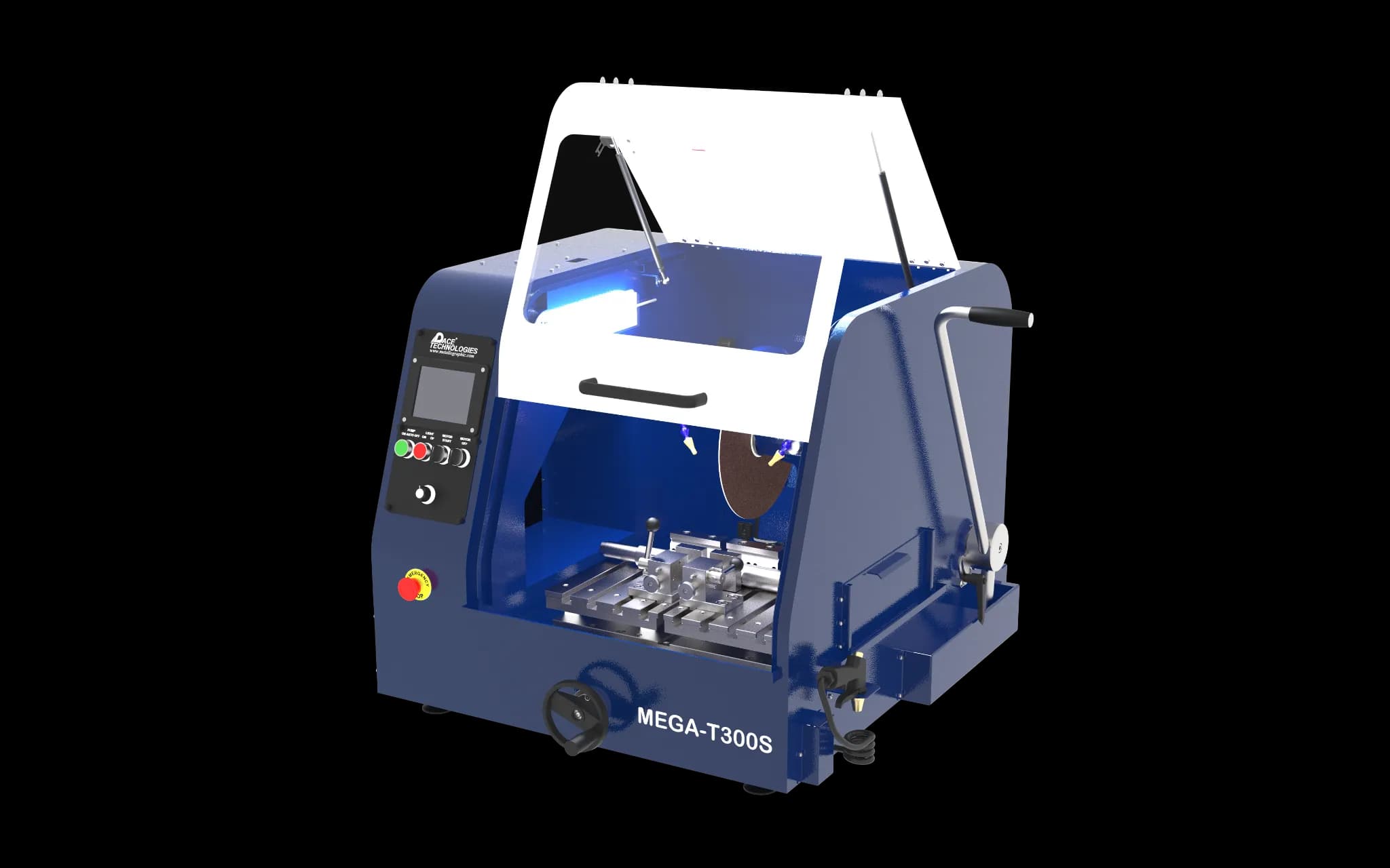
Abrasive cutters for sectioning heat-treated samples. Proper sectioning orientation and cutting parameters are critical to preserve microstructural features and avoid damage.
Mounting
Mounting considerations:
- Hard mounting materials: Use a hard, low-shrinkage resin — glass-filled epoxy compression mounts give the best edge retention (critical for case depth and decarburization measurements); plain phenolic is acceptable only for non-critical work
- Edge retention: Essential for accurate surface measurements
- Sample orientation: Mount so surface of interest is perpendicular to mount base
- Multiple samples: Consider mounting multiple samples together for comparison

Mounting materials and equipment. Hard, low-shrinkage resins such as glass-filled epoxy provide the edge retention essential for case depth measurements and decarburization detection.
Grinding
Standard grinding procedures apply:
- Progressive sequence: 120, 240, 400, 600 grit
- Platen speed: 200-300 RPM with copious water flush
- Rotate 90°: Between each grit to ensure complete scratch removal
- Edge preservation: Use lighter pressure near edges to maintain edge retention
- Adequate time: Spend sufficient time at each step to remove all previous scratches
Polishing
Polishing requirements:
- Standard sequence: 9 μm, 3 μm, 1 μm diamond, then 0.05 μm colloidal silica
- Platen speed: 100-150 RPM for polishing steps
- Finish requirement: 1 μm diamond is the minimum finish for macro-Vickers testing; micro-Vickers and Knoop case-depth profiles require a colloidal silica final polish
- Flatness: Critical for accurate measurements and microhardness testing
- Edge retention: Use lighter pressure and shorter times near edges
- Scratch-free: Essential for microhardness testing and accurate microstructural examination
- Avoid over-polishing: Can create relief and affect flatness
Diamond polishing compounds create scratch-free surfaces required for accurate microhardness testing and microstructural examination.
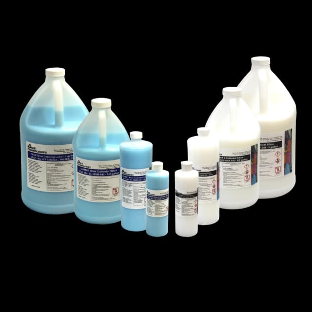
Colloidal silica provides final polishing for mirror-like surfaces essential for microhardness testing, especially Knoop testing for case depth measurements.
Special Considerations
- Retained austenite: May require special preparation to preserve and reveal
- Brittle phases: Some heat-treated materials are brittle and require careful handling
- Multiple phases: Materials with multiple phases may show relief during polishing
- Surface features: Preserve surface features when examining decarburization or case depth
Tip: For case depth measurements, prepare the sample as you would for microhardness testing. Excellent edge retention and flatness are essential.
Etching Considerations
Proper etching is essential for revealing microstructures and heat treatment effects. Different heat treatments and materials require different etchants and techniques.
Common Etchants for Heat-Treated Steels
| Etchant | Composition | Applications | Reveals |
|---|---|---|---|
| Nital | 2-4% HNO₃ in ethanol | Carbon steels, low-alloy steels | Ferrite, pearlite, martensite boundaries |
| Picral | 4% picric acid in ethanol | Carbon steels, pearlite | Pearlite, carbides |
| Vilella's | 1g picric acid, 5ml HCl, 95ml ethanol | Martensite, bainite, martensitic stainless and tool steels | Martensite laths, bainite, prior-austenite grain boundaries |
| Beraha's I | 10ml HCl, 90ml H₂O, 1g K₂S₂O₅ | Color (tint) etching of heat-treated steels | Ferrite, pearlite, bainite, and martensite in distinct colors |
| Sodium Metabisulfite | 10% Na₂S₂O₅ in water | Retained austenite | Retained austenite (white) |
| Klemm's I | 50ml sat. Na₂S₂O₃ (sodium thiosulfate) stock, 1g K₂S₂O₅ | Retained austenite | Retained austenite (colored) |
Etching Techniques
- Light etching: Use shorter times or lighter concentrations for delicate structures or surface features
- Progressive etching: Etch lightly, examine, then re-etch if needed
- Multiple etchants: May need to try different etchants to optimize contrast for specific features
- Etching time: Vary etching time to achieve optimal contrast
- Temperature: Some etchants work better at specific temperatures
Special Considerations
- Retained austenite: Requires special etchants (sodium metabisulfite, Klemm's) to reveal and distinguish from martensite
- Case/core transition: May need to optimize etching to clearly show the transition
- Decarburization: Light etching often works best to reveal the decarburized layer
- Nitrided surfaces: 2% Nital reveals the compound layer (which appears as a white, "glassy" band) and the diffusion zone beneath it; Beraha's tint etch provides color contrast between the compound-layer phases (γ'-Fe₄N vs. ε-Fe₂₋₃N)
For more information on etching techniques, see our Etching Procedures guide.

High-quality etching reagents including Nital, Picral, Vilella's, and specialized etchants for revealing martensite, bainite, and other heat treatment microstructures.
Example Products: Etching Reagentssuitable etching reagents including Nital, Picral, and specialized etchants for heat-treated steels
For purchasing options and product specifications, see commercial supplier website.
Common Heat Treatment Processes and Verification
This section provides specific guidance for verifying common heat treatment processes.
Quench and Temper Verification
Expected microstructure: Tempered martensite (acicular structure)
Verification steps:
- Examine microstructure for tempered martensite
- Check for uniformity throughout
- Verify absence of untempered martensite (if high temper)
- Measure hardness and compare to specifications
- Check for excessive retained austenite (if applicable)
Carburizing Verification
Expected microstructure: High-carbon martensite in case, low-carbon structure in core
Verification steps:
- Measure case depth (microhardness traverse and microstructural)
- Verify case microstructure (high-carbon martensite)
- Check core microstructure (should be appropriate for core composition)
- Measure case and core hardness
- Check for excessive retained austenite in case
- Verify case/core transition is appropriate
- Check for decarburization (should be minimal or absent)
Nitriding Verification
Expected microstructure: Compound layer (white layer) at surface, diffusion zone beneath
Verification steps:
- Measure compound layer thickness (typically 5-25 μm)
- Measure diffusion zone depth
- Verify core microstructure is unchanged
- Check for excessive compound layer (can be brittle)
- Measure surface hardness
- Verify uniformity of nitrided layer
Induction Hardening Verification
Expected microstructure: Martensite in case, original structure in core
Verification steps:
- Measure case depth
- Verify martensite in case
- Check core microstructure (should be original structure)
- Measure case and core hardness
- Verify transition zone is appropriate
- Check for proper case coverage
Annealing Verification
Expected microstructure: Soft structure (pearlite/ferrite or spheroidized)
Verification steps:
- Verify soft microstructure (pearlite/ferrite or spheroidized)
- Check grain size (should be appropriate for annealing type)
- Measure hardness (should be low)
- Verify absence of hard phases (martensite, bainite)
- Check for uniformity
Troubleshooting
Common problems encountered during heat treatment verification and their solutions:
Common Issues and Solutions
| Problem | Causes | Solutions |
|---|---|---|
| Poor edge retention for case depth measurement |
|
|
| Cannot distinguish case/core boundary |
|
|
| Inconsistent case depth measurements |
|
|
| Decarburization difficult to see |
|
|
| Cannot identify microstructure |
|
|
| Surface damage affecting measurements |
|
|
Quality Verification Checklist
Before reporting heat treatment verification results, verify:
- Sample preparation quality: Scratch-free, flat surface, good edge retention
- Etching quality: Proper contrast, not over-etched or under-etched
- Measurement accuracy: Calibrated equipment, proper technique
- Multiple measurements: Take measurements at multiple locations
- Documentation: Clear micrographs with scale bars, detailed notes
- Comparison: Compare with specifications and reference samples
Ready to Verify Heat Treatments?
Now that you understand heat treatment verification techniques, explore our material-specific guides or browse our equipment and consumables for your verification needs.
Case-depth and decarburization measurements are only as defensible as the prep record behind them. For labs that need every reported value traceable to its specific batch, equipment, and operator, a metallography ELN such as Materials Prep keeps the batch, recipe, and micrograph linked.