Castings and Foundry Analysis in Metallography
Overview: Metallographic analysis of cast materials requires specialized techniques to evaluate solidification structures, measure dendrite arm spacing, identify casting defects, and assess grain size control. This guide covers the essential methods for analyzing foundry products.
Introduction to Castings Analysis
Cast materials present unique challenges and opportunities for metallographic analysis. Unlike wrought materials, castings retain the solidification structure from their formation, providing valuable information about the casting process, cooling conditions, and material quality. Understanding these structures is essential for quality control, process optimization, and failure analysis in foundry operations.
The microstructure of cast materials is directly influenced by the solidification process, which creates characteristic features such as dendrites, grain boundaries, and segregation patterns. These features can be analyzed to understand the casting conditions, predict material properties, and identify potential issues.

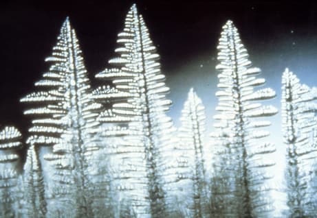
Dendrite structure in cast material. The tree-like crystal growth pattern is characteristic of solidification and provides information about cooling conditions and casting quality.
Key aspects of castings analysis include:
- Solidification structure characterization
- Dendrite arm spacing (DAS) measurement
- Casting defect identification and classification
- Grain size and morphology evaluation
- Segregation and microstructural heterogeneity assessment
Solidification Structure Analysis
Understanding Solidification Structures
Solidification structures in cast materials reflect the conditions under which the material cooled and solidified. The primary solidification structure consists of dendrites, which are tree-like crystalline structures that grow during solidification. The morphology and size of these dendrites provide critical information about cooling rates and casting conditions.

Gray cast iron, 2% nital, 400X magnification. This microstructure shows the solidification structure typical of cast materials, with graphite flakes distributed in the ferrite matrix.
Types of Solidification Structures
1. Columnar Dendrites
Columnar dendrites grow perpendicular to the mold wall and are characteristic of directional solidification:
- Formed under moderate to high cooling rates
- Exhibit directional growth from the mold wall
- Common in sand castings and permanent mold castings
- Indicate unidirectional heat extraction
2. Equiaxed Grains
Equiaxed grains form when solidification occurs uniformly in all directions:
- Formed under rapid cooling or with grain refiners
- No preferred growth direction
- Common in investment castings and die castings
- Generally provide more uniform properties
3. Mixed Structures
Many castings exhibit a combination of columnar and equiaxed zones:
- Columnar zone near mold walls (chill zone)
- Equiaxed zone in the center (equiaxed zone)
- Transition zone between the two
- Zone thickness indicates cooling conditions
Analyzing Solidification Structures
To properly analyze solidification structures:
- Select sections that represent different regions of the casting (surface, mid-thickness, center)
- Prepare samples to reveal the full solidification structure
- Use appropriate etching to highlight dendrite boundaries
- Document the structure at multiple magnifications
- Measure zone thicknesses and transition regions
- Correlate structure with casting process parameters
Interpreting Solidification Structures
The solidification structure provides information about:
- Cooling rate: Faster cooling produces finer structures
- Temperature gradient: Steep gradients favor columnar growth
- Mold material: Metal molds produce different structures than sand molds
- Pouring temperature: Higher temperatures can affect grain size
- Alloy composition: Some elements promote equiaxed structures
Dendrite Arm Spacing Measurement
What is Dendrite Arm Spacing?
Dendrite Arm Spacing (DAS) is the distance between adjacent secondary dendrite arms, measured perpendicular to the primary dendrite stem. DAS is a critical parameter because it directly correlates with cooling rate and affects mechanical properties. Finer DAS (smaller spacing) indicates faster cooling and generally results in improved mechanical properties.
Dendrite structure showing primary and secondary arms. The spacing between secondary arms (DAS) is measured perpendicular to the primary dendrite stem and correlates with cooling rate and mechanical properties.
Types of Dendrite Arm Spacing
1. Primary Dendrite Arm Spacing (PDAS)
The spacing between primary dendrite stems:
- Measured perpendicular to the growth direction
- Larger spacing than secondary arms
- Indicates overall solidification conditions
- Typically ranges from 50 to 500 micrometers
2. Secondary Dendrite Arm Spacing (SDAS)
The spacing between secondary dendrite arms:
- Most commonly measured parameter
- More sensitive to local cooling conditions
- Directly related to mechanical properties
- Typically ranges from 10 to 200 micrometers
Measurement Methods
Linear Intercept Method
The most common method for measuring DAS:
- Prepare a metallographic sample with proper etching to reveal dendrites
- Place a test line or grid over the microstructure image
- Count the number of dendrite arm boundaries intersected by the line
- Measure the total line length
- Calculate DAS = (total line length) / (number of intersections)
- Repeat measurements in multiple locations and orientations
- Report the average and standard deviation
Area Method
An alternative method using area measurements:
- Identify a representative area containing multiple dendrite arms
- Count the number of dendrite arms in the area
- Measure the area
- Calculate DAS based on the square root of (area / number of arms)
- Use this method when dendrites are well-defined and uniformly distributed
Best Practices for DAS Measurement
- Use high-quality sample preparation to clearly reveal dendrite boundaries
- Select representative areas avoiding casting defects
- Make measurements at consistent locations (e.g., mid-thickness)
- Take multiple measurements (minimum 20-30) for statistical validity
- Measure in different orientations to account for anisotropy
- Use calibrated image analysis software when available
- Document measurement conditions and locations
- Report both mean and standard deviation values
Tip: Accurate DAS measurement requires excellent sample preparation and proper etching to clearly reveal dendrite boundaries. Use high-quality polishing to avoid artifacts that could interfere with measurements.
Factors Affecting DAS
DAS is influenced by several factors:
- Cooling rate: Faster cooling produces smaller DAS
- Alloy composition: Some elements affect dendrite growth
- Mold material: Metal molds produce finer DAS than sand molds
- Section thickness: Thinner sections cool faster, producing finer DAS
- Location in casting: Surface regions typically have finer DAS than center
- Heat treatment: Can alter or eliminate dendrite structure
Correlation with Properties
DAS correlates with mechanical properties:
- Strength: Finer DAS generally increases yield and tensile strength
- Ductility: Finer DAS can improve elongation and reduction of area
- Toughness: Finer DAS typically improves impact toughness
- Fatigue: Finer DAS can improve fatigue resistance
- These relationships vary by alloy system and should be established experimentally
Casting Defect Identification
Common Casting Defects
Casting defects can significantly affect material properties and performance. Proper identification and classification are essential for quality control and process improvement. Defects can be categorized by their origin, appearance, and impact on properties.
Porosity Defects
1. Gas Porosity
Spherical or rounded pores caused by trapped gas:
- Appearance: Round or spherical voids, often near the surface
- Causes: Hydrogen pickup, air entrainment, mold gas evolution
- Identification: Smooth, rounded surfaces; may be interconnected
- Impact: Reduces load-bearing area, stress concentrators
- Prevention: Proper degassing, mold venting, reduced moisture
Real porosity vs. preparation artifact: Genuine casting porosity has rounded, smooth interior walls; pull-out artifacts (graphite, inclusions, or fragile material torn out during grinding and polishing) have irregular, freshly-fractured walls. Cracks introduced by grinding tend to be linear and at a fixed orientation to the grinding direction. If in doubt, vacuum-impregnate, prepare more gently, and verify the feature on a second specimen prepared by a different route before reporting it as a casting defect.
2. Shrinkage Porosity
Irregular voids caused by inadequate feeding during solidification:
- Appearance: Irregular, dendritic, or interconnected voids
- Causes: Insufficient riser size, poor gating design, rapid solidification
- Identification: Angular, irregular shapes; often in last-to-freeze regions
- Impact: Significant reduction in mechanical properties
- Prevention: Proper riser design, directional solidification, chills
Inclusion Defects
1. Oxide Inclusions
Non-metallic inclusion particles trapped in the casting:
- Appearance: Dark, irregular particles or stringers
- Causes: Oxidation during melting, poor fluxing, turbulence
- Identification: Dark appearance, often aligned with flow direction
- Impact: Reduces ductility, fatigue strength, and machinability
- Prevention: Proper fluxing, reduced turbulence, protective atmospheres

Oxide inclusion in cast material. Inclusions appear as dark, irregular particles and can significantly affect material properties.
2. Slag Inclusions
Slag particles from the melting process:
- Appearance: Dark, irregular, often glassy appearance
- Causes: Inadequate slag removal, poor skimming
- Identification: Different composition from matrix, often near surface
- Impact: Similar to oxide inclusions
- Prevention: Proper skimming, filtering, clean melting practices
Segregation Defects
1. Inverse Segregation
Concentration of alloying elements near the surface:
- Appearance: Compositional differences visible after etching
- Causes: Interdendritic flow during solidification
- Identification: Etching reveals compositional variations
- Impact: Property variations, potential for localized corrosion
- Prevention: Controlled solidification, reduced pouring temperature
2. Centerline Segregation
Concentration of elements in the center of the casting:
- Appearance: Compositional band in center region
- Causes: Last-to-freeze region, solute rejection
- Identification: Microprobe analysis or selective etching
- Impact: Property variations, potential for cracking
- Prevention: Faster cooling, grain refinement
Surface and Shape Defects
1. Cold Shuts
Incomplete fusion between two metal streams:
- Appearance: Linear defect with oxide film
- Causes: Low pouring temperature, slow filling, multiple gates
- Identification: Oxide film visible, incomplete bonding
- Impact: Significant reduction in strength and fatigue life
- Prevention: Higher pouring temperature, faster filling, single gate
2. Hot Tears
Cracks formed during solidification:
- Appearance: Irregular cracks, often in corners or thick sections
- Causes: Thermal stresses during solidification, mold constraint
- Identification: Intergranular or interdendritic cracks
- Impact: Complete loss of integrity in affected region
- Prevention: Reduced constraint, controlled cooling, proper design
Defect Analysis Techniques
To properly identify and analyze casting defects:
- Examine multiple sections through the defect
- Use appropriate etching to reveal defect boundaries
- Document defect size, shape, and distribution
- Use higher magnification to examine defect surfaces
- Consider using SEM/EDS for composition analysis
- Correlate defect location with casting geometry
- Compare with known defect types and causes
Equipment Note: Metallurgical microscopes are essential for detailed analysis of cast materials. They allow examination of solidification structures, dendrite spacing, and casting defects at various magnifications. Digital imaging capabilities are particularly useful for DAS measurements and defect documentation.
Example Products: Metallurgical Microscopessuitable microscopes for analyzing cast materials, measuring DAS, and identifying casting defects
For purchasing options and product specifications, see commercial supplier website.
Defect Classification Standards
Several standards provide guidance for defect classification:
- ASTM E155 - Standard Reference Radiographs for Inspection of Aluminum and Magnesium Castings
- ASTM E272 - Standard Reference Radiographs for High-Strength Copper-Base and Nickel-Copper Alloy Castings
- ASTM E446 - Standard Reference Radiographs for Steel Castings Up to 2 in. (51 mm) in Thickness
- ISO 11971 - Steel and Iron Castings - Visual Examination of Surface Quality
- Company-specific acceptance criteria based on application
Grain Size Control in Cast Materials
Importance of Grain Size Control
Grain size significantly affects the mechanical properties of cast materials. Fine-grained structures generally provide better strength, ductility, and toughness. Understanding and controlling grain size is essential for producing high-quality castings with consistent properties.
.JPG&w=3840&q=75)
Nodular cast iron, 2% nital, 400X magnification (DIC). This microstructure demonstrates grain structure control in cast materials, with nodular graphite distributed in the ferrite matrix.
Factors Affecting Grain Size
1. Cooling Rate
Faster cooling rates produce finer grains:
- Rapid cooling increases nucleation rate
- Less time for grain growth
- Metal molds produce finer grains than sand molds
- Thinner sections cool faster and have finer grains
- Chills can be used to locally increase cooling rate
2. Grain Refiners
Additions that promote nucleation:
- TiB2 for aluminum alloys
- Zirconium for magnesium alloys
- Rare earth elements for various alloys
- Provide nucleation sites for new grains
- Must be properly distributed in the melt
3. Pouring Temperature
Temperature at which metal is poured:
- Lower pouring temperatures can promote finer grains
- Higher temperatures allow more grain growth
- Must balance with fluidity requirements
- Affects both nucleation and growth
4. Alloy Composition
Some elements naturally promote fine grains:
- Elements that form intermetallic compounds
- Elements that affect solidification range
- Impurities can sometimes act as nucleants
- Composition affects both nucleation and growth
Grain Size Measurement Methods
1. Linear Intercept Method (ASTM E112)
The standard method for grain size measurement:
- Prepare sample with appropriate etching to reveal grain boundaries
- Place test lines or circles over the microstructure
- Count grain boundary intersections
- Calculate mean intercept length
- Convert to ASTM grain size number (G)
- Report average and standard deviation
See our grain size calculator tool for assistance with these calculations.
2. Planimetric Method
Counting grains within a known area:
- Count the number of grains in a known area
- Account for grains on boundaries (count as 0.5)
- Calculate grains per unit area
- Convert to ASTM grain size number
3. Comparison Method
Comparing with standard charts:
- Use standard grain size charts (ASTM E112)
- Compare microstructure with chart images
- Estimate grain size number
- Less accurate but faster than measurement methods
- Useful for quick assessments
Grain Size Control Techniques
1. Process Control
- Control pouring temperature within specified range
- Optimize mold design for desired cooling rates
- Use chills to increase local cooling rates
- Control mold preheat temperature
- Optimize gating and riser design
Tip: The relationship between cooling rate and grain size follows the Hall-Petch relationship, where finer grains generally provide improved mechanical properties. Controlling the casting process parameters directly affects the final grain structure.
2. Grain Refinement
- Add appropriate grain refiners to the melt
- Ensure proper distribution and dissolution
- Control addition temperature and time
- Monitor grain refiner effectiveness
- Adjust addition rates based on results
3. Heat Treatment
- Solution treatment can homogenize structure
- Recrystallization can refine grains in some cases
- Cannot refine as-cast grains but can modify structure
- Use appropriate temperatures and times
- Consider effect on other properties
Grain Size Specifications
Grain size requirements vary by application:
- General castings: ASTM 1-4 (coarse to medium)
- High-performance castings: ASTM 4-7 (medium to fine)
- Precision castings: ASTM 5-8 (fine to very fine)
- Specifications often include maximum grain size
- May specify different requirements for different regions
- Consider both average and maximum grain size
Grain Size and Properties
The Hall-Petch relationship describes the effect of grain size on strength:
- Finer grains increase yield strength
- Finer grains generally improve ductility
- Finer grains improve toughness and impact resistance
- Finer grains can improve fatigue properties
- Relationship varies by alloy and condition
- Must balance with other property requirements
Sample Preparation for Castings
Special Considerations for Cast Materials
Cast materials require careful sample preparation to preserve the solidification structure and reveal casting defects. The preparation process must avoid introducing artifacts that could be mistaken for casting features.
Sectioning
When sectioning cast samples:
- Select locations that represent different regions (surface, mid-thickness, center)
- Section perpendicular to expected solidification direction when possible
- For abrasive cutoff, use a wheel speed of roughly 2,500-4,500 surface feet per minute (SFM) with a light feed to avoid excessive heating
- Preserve casting defects - avoid cutting through critical defects
- Document section location relative to casting geometry
- Use coolant to prevent thermal damage
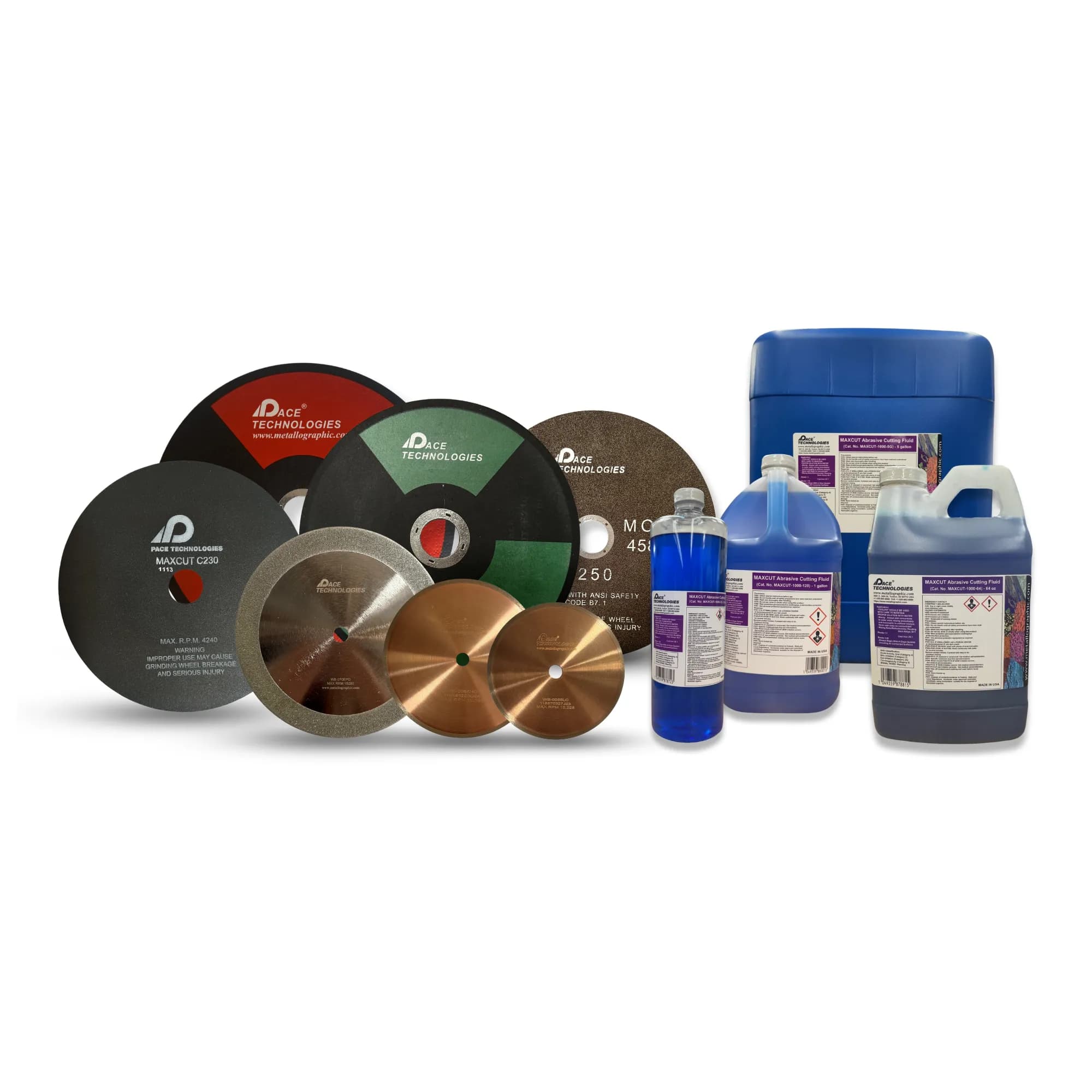
Sectioning equipment and consumables. Proper sectioning is critical for preserving casting features and defects during sample preparation.
Refer to our sectioning guide for detailed techniques.
Mounting
Mounting considerations for castings:
- Use appropriate mounting material to preserve edges
- Consider vacuum impregnation for porous castings
- Protect casting defects during mounting
- Ensure good edge retention for surface analysis
- Use compression mounting for most applications
- Consider castable mounting for delicate samples

Mounting materials for cast samples. Vacuum impregnation may be necessary for porous castings to preserve defect structure.
See our mounting guide for more information.
Example Products: Mounting MaterialsCompression and castable mounting materials suitable for cast materials, including vacuum impregnation systems for porous samples
For purchasing options and product specifications, see commercial supplier website.
Grinding and Polishing
Grinding and polishing cast materials:
- Follow standard progressive grinding procedures
- Use appropriate pressure to avoid pulling out inclusions
- Be careful around porosity - avoid filling with abrasive
- Use diamond polishing for hard phases
- Achieve scratch-free surface for accurate analysis
- Clean thoroughly between steps to avoid contamination
- Use final polishing to remove deformation

Grinding and lapping consumables. Progressive grinding removes sectioning damage while preserving casting features like dendrites and defects.
See our grinding and polishing guides for detailed procedures.
Preserving Casting Features
Special techniques to preserve casting features:
- Avoid excessive polishing that could round off dendrite arms
- Use appropriate polishing cloths to maintain feature definition
- Be careful not to pull out inclusions or fill porosity
- Use low nap cloths for final polish to maintain sharp features
- For cast irons, keep polishing times to the minimum needed — every extra interval risks graphite pull-out and flake distortion, which exaggerates apparent porosity
- Consider using vibratory polishing for delicate structures
- Document any preparation artifacts
Etching Techniques for Cast Materials
Etching Objectives
Etching cast materials serves several purposes:
- Reveal grain boundaries and grain size
- Highlight dendrite structure and DAS
- Distinguish different phases and constituents
- Reveal segregation patterns
- Highlight casting defects
- Show microstructural heterogeneity
Common Etchants for Cast Materials
Aluminum Castings
Common cast aluminum alloys include 6061 and 7075, though many foundry-specific alloys are used. Etching techniques vary by alloy composition:
- Keller's reagent: Reveals grain boundaries and phases
- Weck's reagent: Colors different phases
- Poulton's reagent: For silicon phase identification
- Anodizing: For grain structure and orientation

Aluminum-silicon cast alloy, Keller's reagent, 400X magnification. This microstructure demonstrates proper etching to reveal grain boundaries and silicon phase distribution in cast aluminum.
Steel and Cast Iron Castings
Cast steels and cast irons including ductile cast iron (nodular iron) and white cast iron require specific etching techniques. For cast irons, always examine the sample in the as-polished (unetched) condition first to assess graphite morphology, size, and distribution per ASTM A247 — etching obscures the graphite assessment. Then etch for the matrix structure:
- Nital (2-5%): Standard first etch for the ferrite/pearlite matrix (5-15 s swab for cast irons)
- Picral (4%): Follow-up etch that sharpens pearlite and darkens cementite; often used sequentially after Nital
- Vilella's reagent or 4% Picral: For carbide morphology in white (high-Cr) irons
- Beraha's tint etch: Color contrast revealing ferrite/pearlite/bainite distribution

White cast iron, as-polished, 400X magnification. Cast iron microstructures require appropriate etching to reveal the solidification structure and phase distribution.

Gray cast iron, 2% nital, 1000X magnification. High magnification reveals the detailed structure of graphite flakes and the ferrite/pearlite matrix.
Example Products: Etchants and Chemical ReagentsChemical etchants for revealing microstructures in cast materials including aluminum, steel, and cast iron alloys
For purchasing options and product specifications, see commercial supplier website.
Copper Alloy Castings
Cast copper alloys including bronzes and brasses require specific etching techniques:
- Ammonium hydroxide + hydrogen peroxide: For general structure
- Potassium dichromate: For phase identification
- Ferric chloride: For alpha and beta phases
%20400X.JPG&w=3840&q=75)
Manganese-aluminum bronze, alcoholic ferric chloride, 400X magnification. This cast bronze alloy shows the complex phase structure typical of cast copper alloys.
Etching for Specific Features
Revealing Dendrite Structure
To clearly reveal dendrite boundaries:
- Use etchants that attack interdendritic regions
- Control etching time to avoid over-etching
- May require multiple etching steps
- Use appropriate magnification to observe structure
- Consider using color etchants for better contrast
Highlighting Segregation
To reveal segregation patterns:
- Use selective etchants that attack segregated regions
- Color etchants can highlight compositional differences
- May require microprobe analysis for confirmation
- Document etching conditions for reproducibility
Defect Identification
Etching can help identify casting defects:
- Oxide films in cold shuts become more visible
- Porosity boundaries are highlighted
- Inclusions stand out from the matrix
- Hot tears show as etched cracks
- Use appropriate etchants for the alloy system
See our etching procedures guide and etchant database for more information on specific etchants.
Standards and References
Several standards provide guidance for castings analysis:
- ASTM E3 - Standard Practice for Preparation of Metallographic Specimens
- ASTM E112 - Standard Test Methods for Determining Average Grain Size
- ASTM A247 - Standard Test Method for Evaluating the Microstructure of Graphite in Iron Castings
- ASTM E155 - Standard Reference Radiographs for Inspection of Aluminum and Magnesium Castings
- ASTM E446 - Standard Reference Radiographs for Steel Castings Up to 2 in. (51 mm) in Thickness
- ASTM E883 - Standard Guide for Reflected-Light Photomicrography
- ASTM E2283 - Standard Practice for Extreme Value Analysis of Nonmetallic Inclusions in Steel and Other Microstructural Features
- ASM Handbook Volume 9 - Metallography and Microstructures
- ASM Handbook Volume 15 - Casting
- ISO 11971 - Steel and Iron Castings - Visual Examination of Surface Quality
Refer to our ASTM standards reference for more information.
Conclusion
Metallographic analysis of cast materials provides essential information about solidification structure, casting quality, and material properties. Understanding how to analyze solidification structures, measure dendrite arm spacing, identify casting defects, and evaluate grain size is critical for quality control and process optimization in foundry operations.
Key points for successful castings analysis:
- Proper sample preparation to preserve casting features
- Appropriate etching to reveal structures and defects
- Systematic measurement of DAS and grain size
- Thorough identification and classification of defects
- Correlation of microstructural features with casting process
- Documentation of all observations and measurements
For more information on metallographic techniques, see our guides on sectioning, grinding, polishing, etching, and microstructural analysis.